Testing system for battery protection board and testing method thereof
A battery protection board and test system technology, applied in the direction of electronic circuit testing, etc., can solve the problems of low test efficiency and complex test process, and achieve the effect of improving test efficiency and simplifying the test process.
- Summary
- Abstract
- Description
- Claims
- Application Information
AI Technical Summary
Problems solved by technology
Method used
Image

Examples
Embodiment Construction
[0026] Embodiments of the present invention will now be described with reference to the drawings, in which like reference numerals represent like elements.
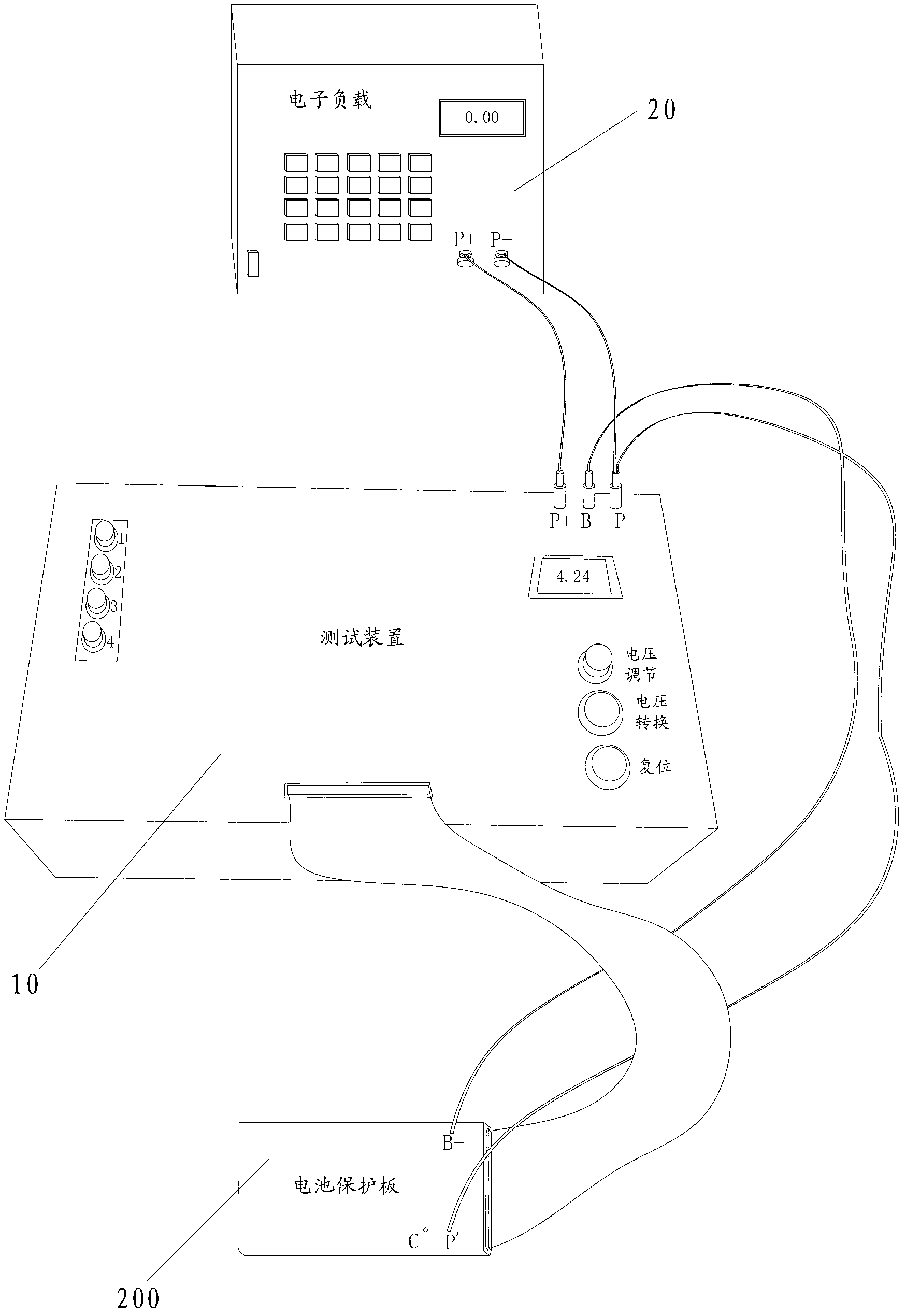
[0027] refer to figure 1 , the test system for the battery protection board of the present invention includes an electronic load 20 and a test device 10, the electronic load 20, the test device 10 and the battery protection board 200 are connected to form a test loop.
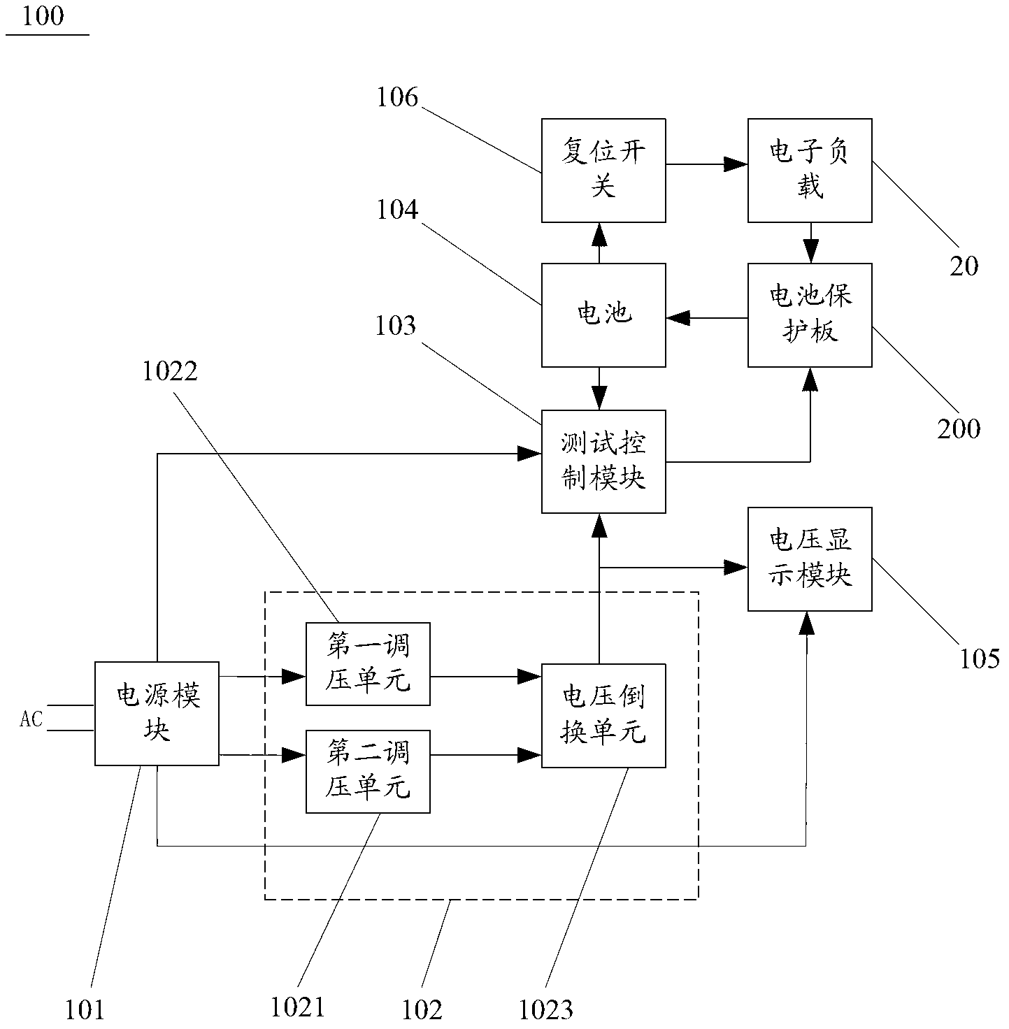
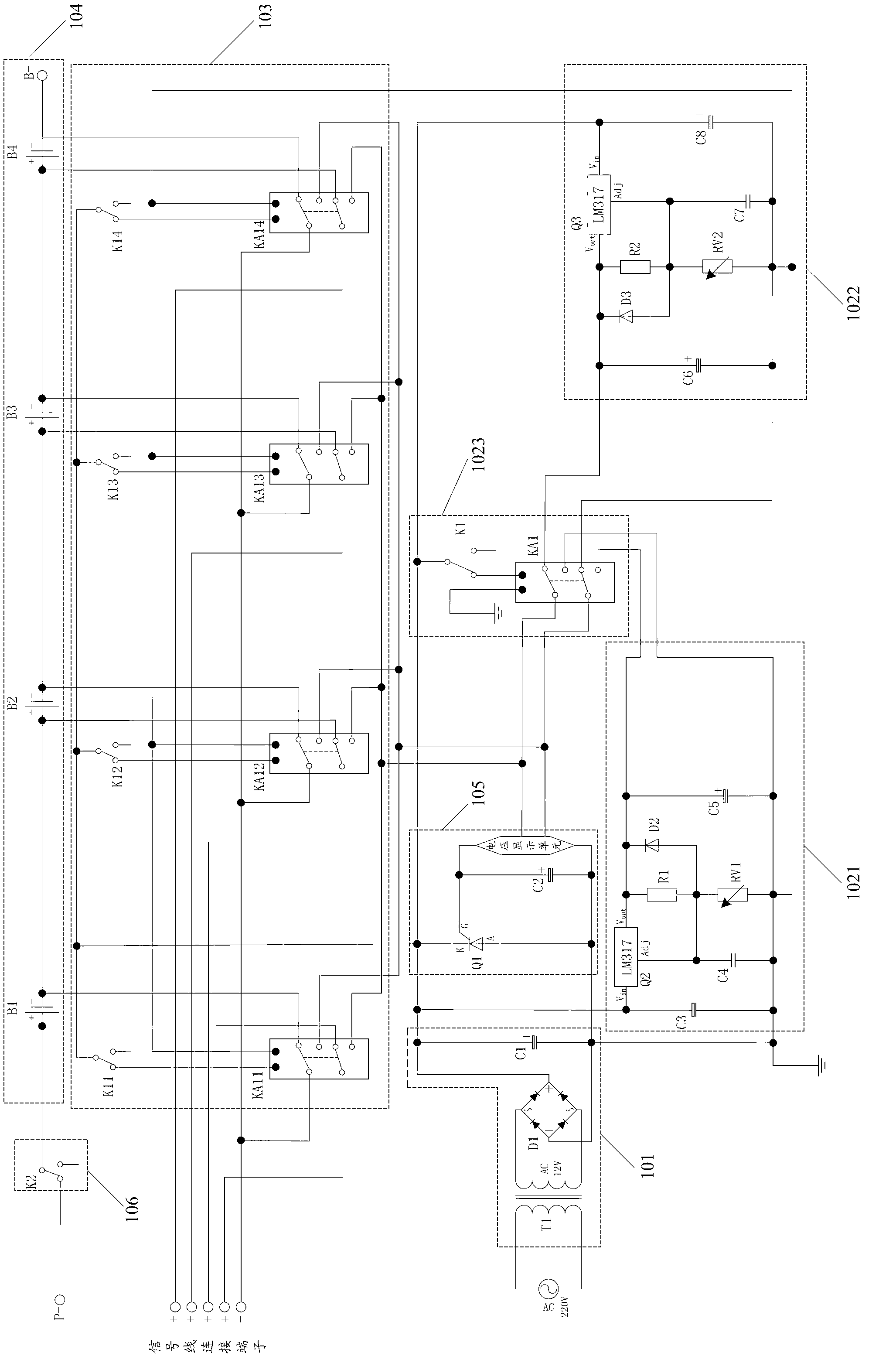
[0028] combine figure 1 , figure 2 and image 3 , the test device 10 includes a power supply module 101 , a voltage regulation module 102 , a test control module 103 , a battery 104 , a voltage display module 105 and a reset switch 106 .
[0029] Specifically, the battery 104 includes battery cells B1 ( B2 , B3 and B4 ), and the battery cells B1 ( B2 , B3 and B4 ) are connected in series.
[0030] Specifically, the power module 101 includes a transformer T1, a bridge rectifier D1 and a capacitor C1. The input terminal of the transformer T1 is connect...
PUM
 Abstract
Description
Claims
Application Information
PatSnap Eureka turns technology decisions into work you can execute. Powered by our Innovation Knowledge Graph, it runs expert workflows across engineering, life sciences, materials and intellectual property. Get your review-ready output in minutes.


