Method of improving parallel resistance in photovoltaic cells

A battery and silicon chip technology, applied in the direction of circuits, electrical components, sustainable manufacturing/processing, etc., can solve the problem that selective emitter batteries cannot be applied on a large scale, so as to improve parallel resistance, reduce parallel failure ratio, and improve The effect of conversion efficiency

Active Publication Date: 2013-09-18
TRINA SOLAR CO LTD
View PDF6 Cites 2 Cited by
  • Summary
  • Abstract
  • Description
  • Claims
  • Application Information

AI Technical Summary

Problems solved by technology

[0009] The purpose of the present invention is to invent a method for improving the parallel resistance of selective emitter junction cells on the basis of the above preparation method 4), so as to solve the urgent problem that selective emitter cells in the photovoltaic field cannot be applied on a large scale

Method used


Image

  • Method of improving parallel resistance in photovoltaic cells
  • Method of improving parallel resistance in photovoltaic cells
  • Method of improving parallel resistance in photovoltaic cells

Examples


experiment example

[0037] Experimental examples and corresponding experimental data are given below.

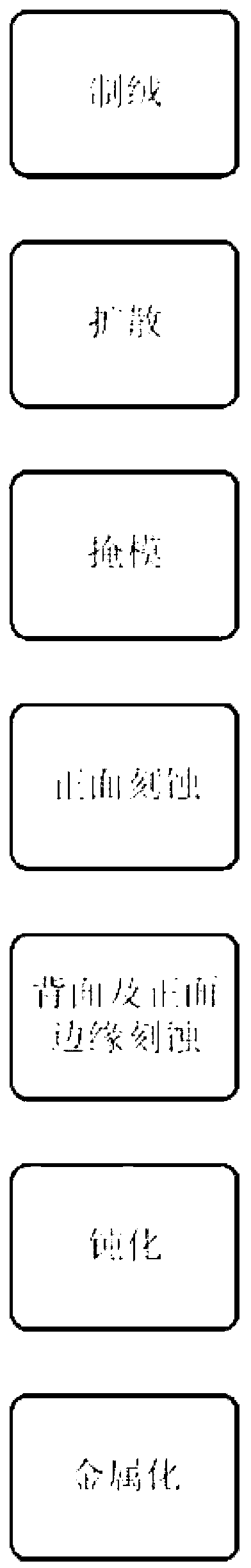
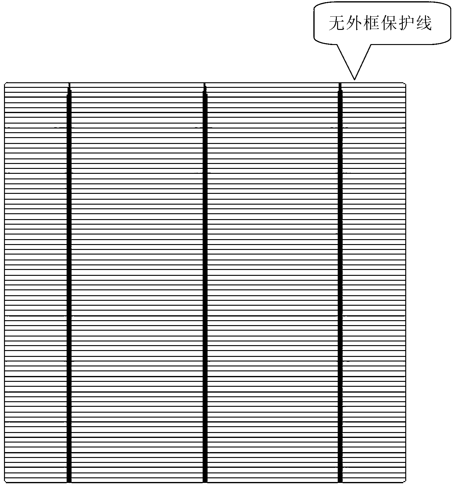
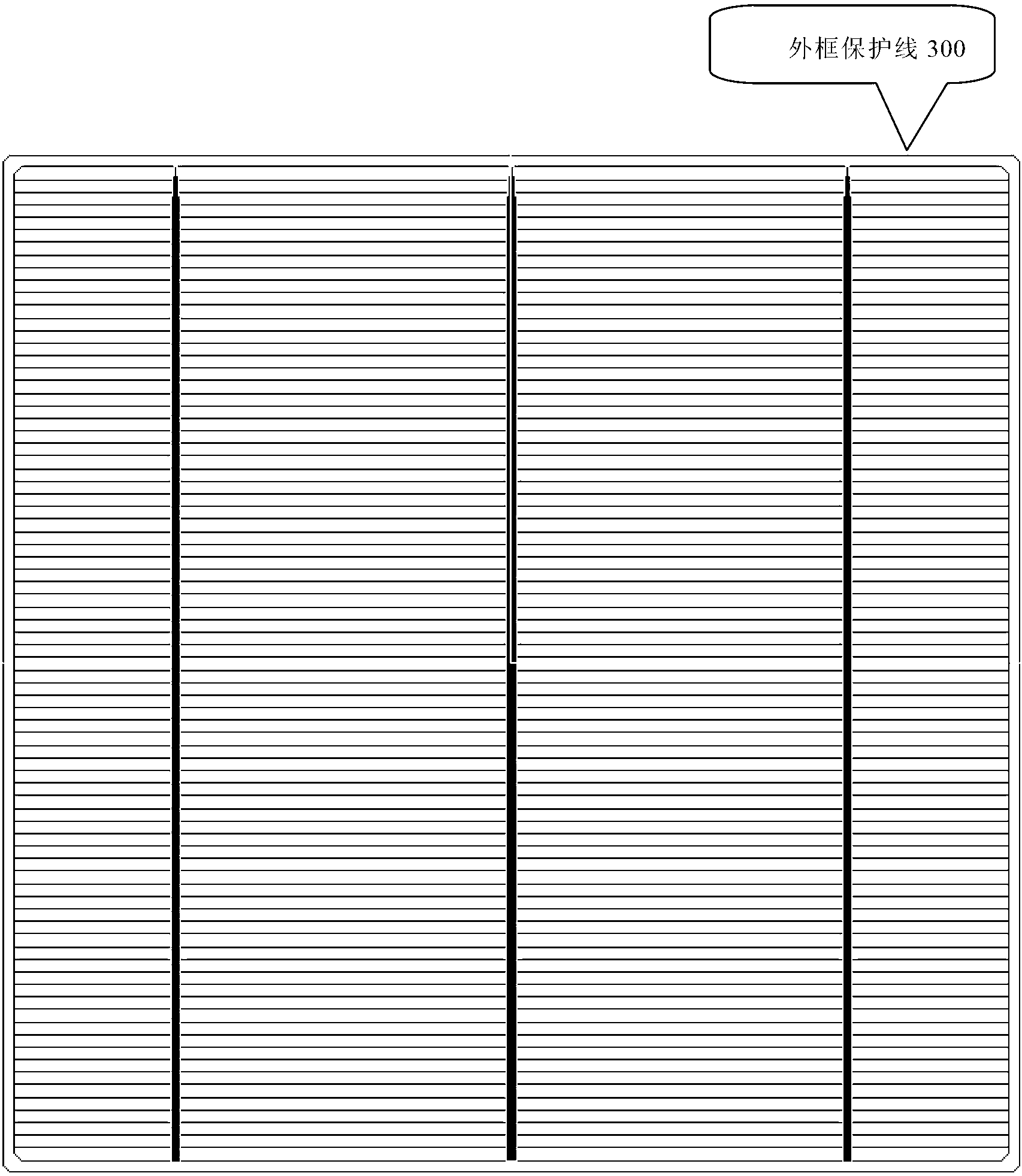
[0038] 1) A batch of polysilicon wafers with a size of 156 mm are acid-textured, and phosphorus is diffused on the front surface. The square resistance after diffusion is 50 ohm / sq. For the film, in addition to adding a mask to the area to be metallized on the front, a mask of a square outer frame is also printed on the edge of the front. The outer frame is 0.2mm away from the edge of the silicon wafer, and the width of the outer frame is 0.25mm.

[0039] 2) Pass the above silicon wafers through HF / HNO in sequence 3 Groove and KOH / BDG groove for surface etching and masking treatment, and then through HCl groove and H 2 Dry the surface with hot air after the O slot. The square resistance of the non-masked area after surface etching is 95ohm / sq.

[0040] 3) Pass the above silicon wafers through HF / HNO in sequence 3Groove and KOH / BDG groove for backside etching and front edge etching, and then...


PUM


Abstract

The invention discloses a method of improving parallel resistance in photovoltaic cells. A production process of a selective emitter junction cell includes: producing a silicon wafer comprising an emitter junction; setting a mask on the front surface of the silicon wafer to protect an area to be metalized on the front surface of the silicon wafer and the edge of the front surface of the silicon wafer; etching the front surface of the silicon wafer; removing the mask; and etching the edges of the back and front surfaces of the silicon wafer. The mask comprises a mask outer frame disposed at the edge of the front surface of the silicon wafer. The invention further discloses a selective emitter junction cell produced by the production process.

Description

technical field [0001] The invention belongs to the photovoltaic field. Specifically, the present invention relates to a method for increasing the parallel resistance of photovoltaic cells. Background technique [0002] Selected emitter (SE) battery preparation technology is a highly efficient photovoltaic cell preparation technology that has been gradually promoted in recent years. Its principle is to use the re-diffusion of the grid line area on the front surface of the battery (to widen the sintering window and reduce contact resistance). , The structural design of light diffusion in other light-receiving areas on the front surface (reducing the surface minority carrier recombination rate) is used to achieve the purpose of improving the battery efficiency, and the improvement range is about 0.3% (absolute value). [0003] Parallel resistance (Rsh for short) is an important evaluation index of photovoltaic cells, which can measure the ability of p / n junction to resist bac...

Claims


Application Information

Patent Timeline
Patent Type & Authority Applications(China)
IPC IPC(8): H01L31/18
CPCY02P70/50
Inventor 熊震邓伟伟卫志敏祁宏山
Owner TRINA SOLAR CO LTD
Why Eureka
Try Eureka