Organic solar cell comprising an intermediate layer with asymmetrical transport properties

An intermediate layer, asymmetric technology, applied in the direction of circuits, photovoltaic power generation, electrical components, etc., can solve problems such as there is no known solution to improve parallel resistance

Active Publication Date: 2006-07-19
MERCK PATENT GMBH
View PDF1 Cites 0 Cited by
  • Summary
  • Abstract
  • Description
  • Claims
  • Application Information

AI Technical Summary

Problems solved by technology

[0004] But so far there is no known suitable

Method used


Image

  • Organic solar cell comprising an intermediate layer with asymmetrical transport properties

Examples


Embodiment Construction

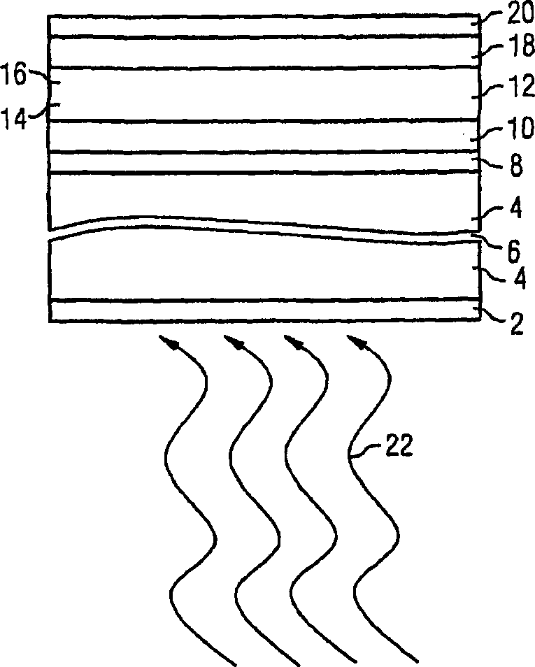
[0023] figure 1 A cross section of a solar cell according to an embodiment of the present invention is shown. The solar cell is seated on a carrier material or substrate 4 . The substrate 4 can be made of glass, plastic, crystal and other materials. The substrate 4 is shown with a burst line 6 to show that the thickness of the substrate 4 is not critical to the invention and is variable. The substrate serves only to provide the solar cell with a corresponding mechanical stability and, if necessary, to provide surface protection. The side of the substrate facing the incident light is coated with an anti-reflection layer 2 to avoid loss due to reflection.

[0024] The first layer 8 on the substrate is the electrode of the solar cell. It is not important whether the electrode is a cathode or an anode.

[0025] It is assumed here, without limitation, that light enters the solar cell shown through the substrate 4 from below. Therefore, the first electrode 8 should consist of,...


PUM


Abstract

The solar cell has an antireflection layer (2) on the outside of a transparent plastics, glass or crystalline substrate (4). A first layer on the inner side of the substrate is an electrode (8). It may act either as the cathode or the anode and may be made of aluminum, copper or ITO (Indium Tin Oxide). A first intermediate layer (10) has an asymmetrical conductivity and acts as an electron acceptor. It also acts as an optical antireflection layer. The next active layer (12) has an electron acceptor side (14) contacting the first intermediate layer and an electron donor side (16) contacting a second intermediate layer (18) and an electrode layer (20).

Description

technical field [0001] The invention relates to an organic solar cell, which has a photosensitive layer composed of two molecular components, an electron donor and an electron acceptor, and has electrodes arranged on both sides of the photosensitive layer. Background technique [0002] For organic solar cells and photodetectors (especially bulk heterojunction Polymer-Solarzellen, high-capacity heterojunction polymer solar cells), a decrease in parallel resistance with increasing illumination intensity has been noted. This phenomenon is called photo-shunt. Light shunting leads to a decrease in fill factor and thus in solar cell efficiency. [0003] A method of increasing series resistance and contact selectivity is disclosed in WO 01 / 84645A1. [0004] To date, however, no suitable solution for increasing the parallel resistance is known. Contents of the invention [0005] Therefore, the technical problem to be solved by the present invention is to increase the parallel r...

Claims


Application Information

Patent Timeline
IPC IPC(8): H01L51/42H01L51/46H01L31/042H01L51/00H01L51/30
CPCH01L51/0036H01L51/0037H01L51/0078H01L51/0092B82Y10/00H01L51/0046H01L51/441H01L51/422H01L51/4253Y02E10/549H01L51/4246H01L51/0053H01L51/44H01L51/0047H10K85/113H10K85/1135H10K85/211H10K85/215H10K85/621H10K85/311H10K85/381H10K30/15H10K30/211H10K30/30H10K30/353H10K30/81H01L31/04H10K30/00H10K30/80
Inventor 克里斯托弗·布拉贝克克里斯托弗·沃尔多夫
Owner MERCK PATENT GMBH
Why Eureka
Try Eureka