Battery system and temperature control method therefor

A temperature control method and battery system technology, applied to secondary batteries, battery pack components, circuits, etc., can solve problems such as temperature uniformity of difficult battery modules, and achieve the effect of temperature uniformity

Inactive Publication Date: 2013-09-18
HITACHI LTD
View PDF4 Cites 57 Cited by
  • Summary
  • Abstract
  • Description
  • Claims
  • Application Information

AI Technical Summary

Problems solved by technology

[0005] However, the technology disclosed in Patent Document 1 is a configuration that includes a set of cooling devices and cooling medium circulation devices for one cooling plate. The cooling plate cools a plurality of battery modules, and it may be difficult to equalize the temperature of the plurality of cooling plates, that is, the temperature of the plurality of battery modules.

Method used


Image

  • Battery system and temperature control method therefor
  • Battery system and temperature control method therefor
  • Battery system and temperature control method therefor

Examples


no. 1 Embodiment approach 〕

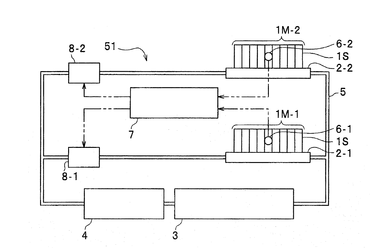
[0036] figure 1 It is a configuration diagram of the battery system according to the first embodiment of the present invention. figure 1 In this embodiment, the battery system 51 includes two battery modules 1M-1 and 1M-2 to be temperature controlled, two cooling members, a cooling device 3, a cooling medium circulation mechanism 4, a cooling medium flow path 5, and a control system. Part 7.

[0037] here, in figure 1 In , the cooling member located on the lower side is referred to as the first stage, and the cooling member located on the upper side is referred to as the second stage. The cooling means in the first stage includes a cooling plate 2-1 and a flow regulator 8-1, and controls the temperature of the battery module 1M-1. In addition, the second-stage cooling means includes a cooling plate 2-2 and a flow regulator 8-2, and controls the temperature of the battery module 1M-2.

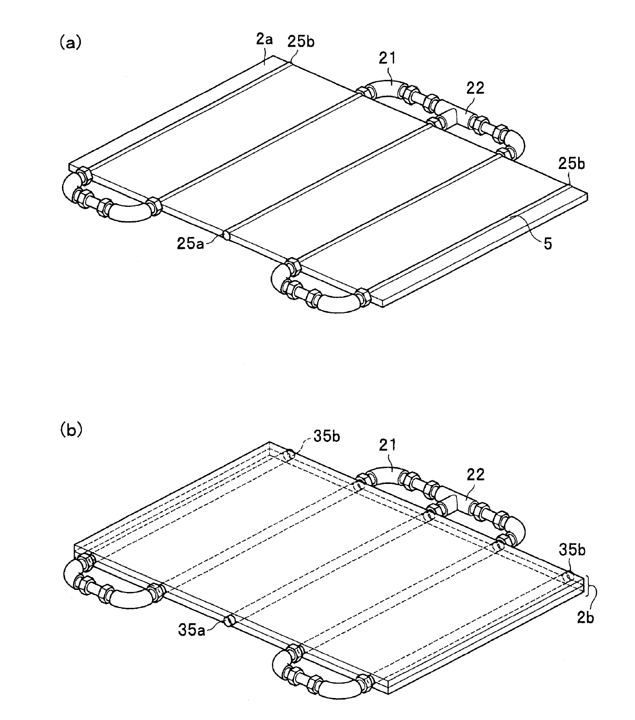
[0038] The cooling plate 2-1 and the cooling plate 2-2 are cooling members referred to i...

no. 2 Embodiment approach 〕

[0064] Next, the battery system and its temperature control method according to the second embodiment of the present invention will be described. Figure 5 It is a configuration diagram of a battery system according to a second embodiment of the present invention. Figure 5 In this embodiment, the battery system 53 includes N battery modules 11M-1 to 11M-N (N is an integer greater than or equal to 2, and the first embodiment is a configuration when N=2) to be temperature-controlled, and N cooling components, a cooling device 13 , a cooling medium circulation mechanism 14 , a cooling medium flow path 15 , and a control unit 17 .

[0065] Here, like the first embodiment, battery modules 11M-1 to 11M-N are formed by connecting a plurality of unit cells in series, and are placed on cooling plates 12-1 to 12-N, respectively. In addition, similarly to the first embodiment, temperature sensors 16 - 1 to 16 -N are provided at substantially the center of the battery modules 11M- 1 to ...


PUM


Abstract

Provided are a battery system and temperature control method therefor capable of suppressing excessive cooling of a battery module, diminishing a temperature variance, and leveling the temperatures of plural battery modules. In the battery system including cooling units each of which is provided with a cooling plate (2-1, 2-2) which includes a flow channel through which a refrigerant flows and on which a battery module that is an object of temperature control (1M-1, 1M-2) is placed, and a flow rate adjustment device (8-1, 8-2) that adjusts the flow rate of the refrigerant that flows through the flow channel, temperature sensors (6-1, 6-2) that individually sense the temperatures of the battery modules, and a refrigerant circulation mechanism (4) that branches out the refrigerant into the flow channels accompanying the cooling units, and joins and circulates the refrigerants coming from the flow channels, a control unit (7) adjusts the refrigerant flow rates using the flow rate adjustment devices (8-1, 8-2) according to the temperatures, which are sensed by the temperature sensors (6-1, 6-2), for each of the cooling units.

Description

technical field [0001] The present invention relates to a battery system including a plurality of batteries and a temperature control method for the battery system. Background technique [0002] The battery system is used as a storage of electric power generated by natural energy, a power source of a smart grid, a backup power source of a facility, etc. It is also possible to construct a megawatt-class large-scale storage battery system by combining multiple battery systems. A secondary battery used as a power source of such a system generates heat during charging and discharging, and since deterioration of the battery accelerates at a high temperature and shortens its life, it needs to be cooled. In addition, when the temperature is extremely low, since the resistance value in the battery becomes high and affects the performance of the battery, it is required that overcooling does not occur. In addition, in a battery system containing a plurality of batteries, there is a p...

Claims


Application Information

Patent Timeline
Patent Type & Authority Applications(China)
IPC IPC(8): H01M10/50H01M50/209
CPCH01M10/482H01M10/486H01M10/615H01M10/633H01M10/6567Y02E60/10H01M50/209
Inventor 田中融山内晋井上健士
Owner HITACHI LTD
Why Eureka
Try Eureka