Solid laser with annular polarization compensation

A solid-state laser and polarization technology, which is applied to lasers, laser components, phonon exciters, etc., can solve the problems of increasing resonant cavity depolarization loss, laser power and laser mode decline, and achieve high electro-optical conversion efficiency and high peak value Effect of power, high beam quality

Inactive Publication Date: 2013-09-18
WUHAN MEIMAN TECH
View PDF7 Cites 6 Cited by
  • Summary
  • Abstract
  • Description
  • Claims
  • Application Information

AI Technical Summary

Problems solved by technology

However, when the above device is applied to a laser composed of an isotropic laser medium such as Nd:YAG or an anisotropic gain medium, no matter whether it operates in a continuous state or a Q-switched pulse state, due to the thermally induced birefringence of the laser crystal effect, will greatly increase the depolarization loss of the resonator, resulting in a significant decrease in the output laser power and laser mode of the laser

Method used


Image

  • Solid laser with annular polarization compensation
  • Solid laser with annular polarization compensation
  • Solid laser with annular polarization compensation

Examples


Embodiment 1

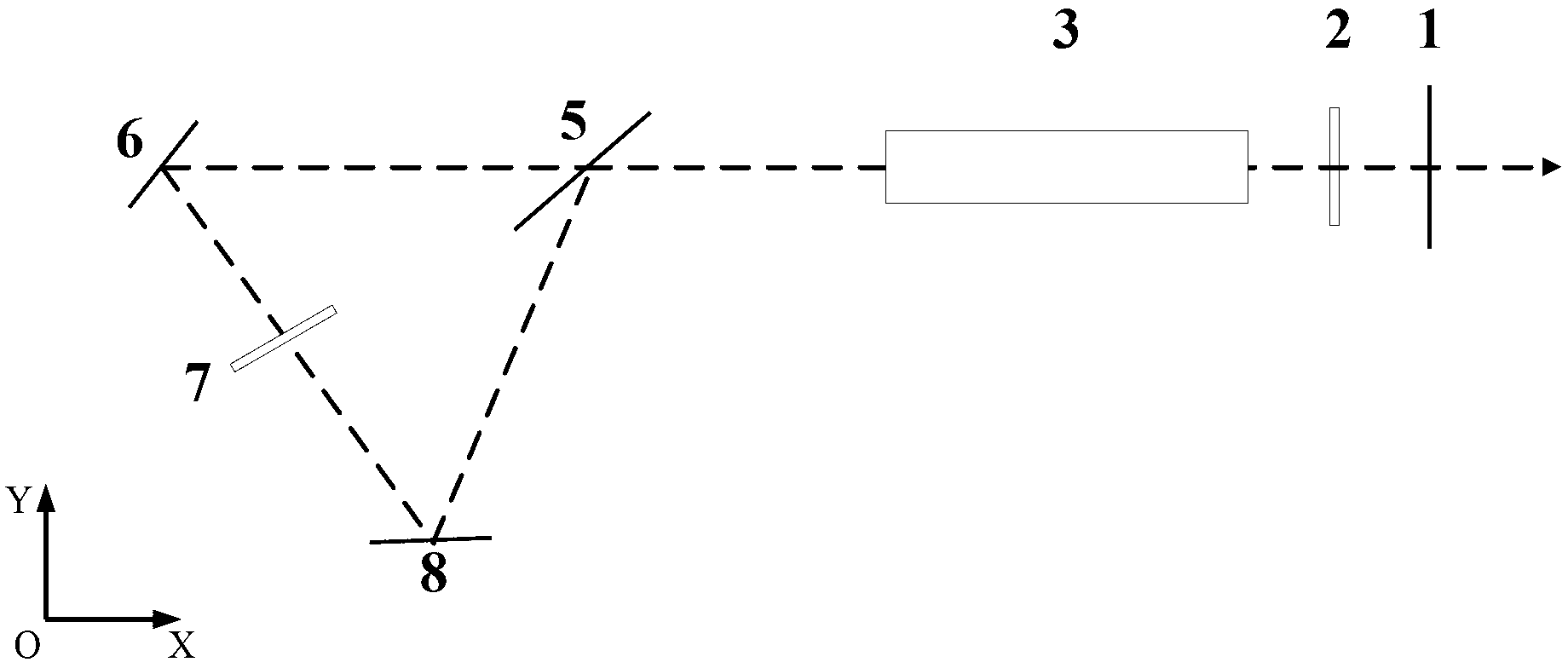
[0019] figure 1 As shown, the laser includes a laser output mirror 1 , a λ / 4 wave plate 2 , a laser gain medium 3 , a polarizing beam splitter 5 , a first reflection mirror 6 , a λ / 2 wave plate 7 , and a second reflection mirror 8 . Wherein the laser output mirror 1, the polarization beam splitter mirror 5, the first mirror 6, and the second mirror 8 constitute a laser resonant cavity. The optical path between the laser beam splitter 5 and the laser output 1 is the main optical path of the resonant cavity.

[0020] The laser output mirror 1 is a semi-transparent and half-reflective mirror, which realizes laser output while improving sufficient reflection and amplification of the resonant cavity.

[0021] The λ / 4 wave plate 2 is located on the main optical path of the laser resonator, and controls the ratio and composition of the polarization state of the laser output from the resonator.

[0022] The laser gain medium 3 is located on the main optical path of the laser resonat...

Embodiment 2

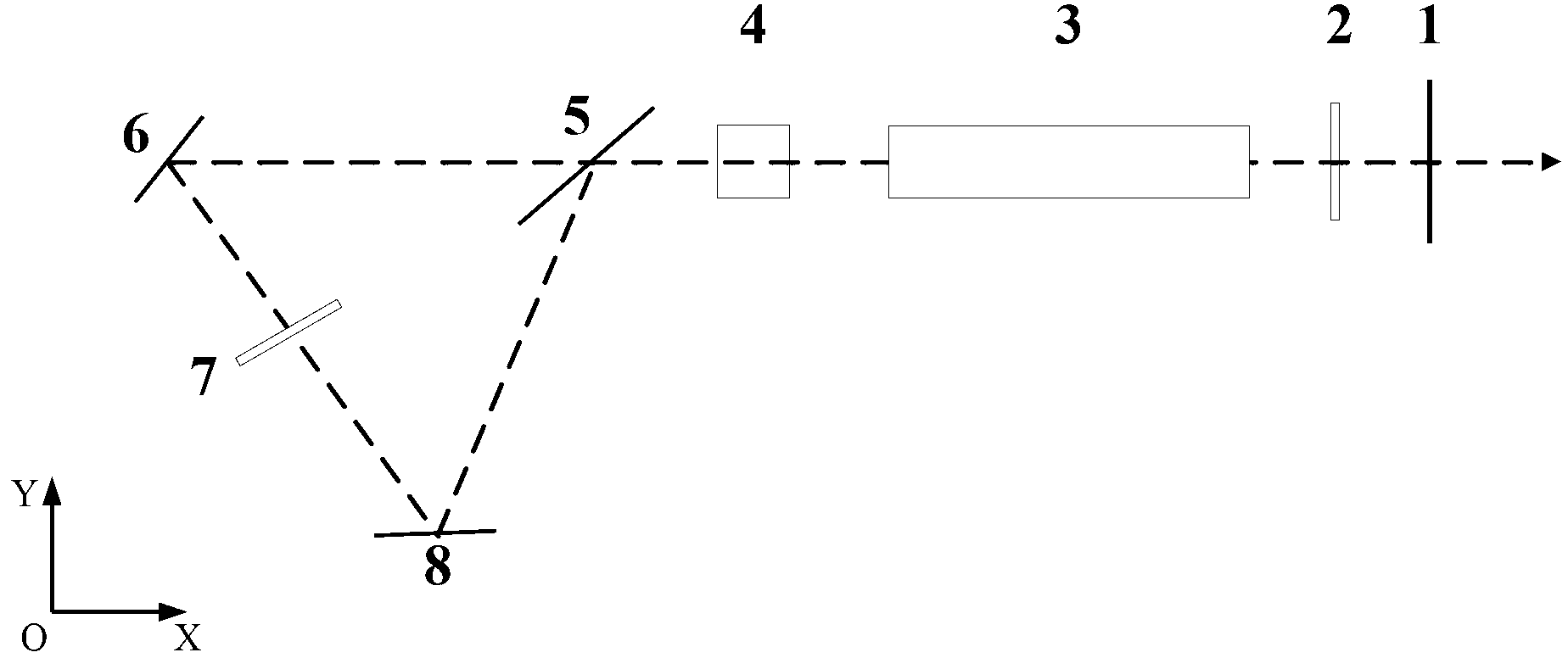
[0028] figure 2 An application example of the laser of the present invention under Q-switched operation is given, such as figure 2 As shown, the laser includes a laser output mirror 1, a λ / 4 wave plate 2, a laser gain medium 3, a Q-switching device 4, a polarizing beam splitter 5, a first reflector 6, a λ / 2 wave plate 7, and a second reflector Mirror 8. Wherein the laser output mirror 1, the polarization beam splitter mirror 5, the first mirror 6, and the second mirror 8 constitute a laser resonant cavity. The optical path between the laser beam splitter 5 and the laser output 1 is the main optical path of the resonant cavity.

[0029] The laser output mirror 1 is a semi-transparent and half-reflective mirror, which realizes laser output while improving sufficient reflection and amplification of the resonant cavity.

[0030] The λ / 4 wave plate 2 is located on the main optical path of the laser resonator, and controls the ratio and composition of the polarization state of ...

Embodiment 3

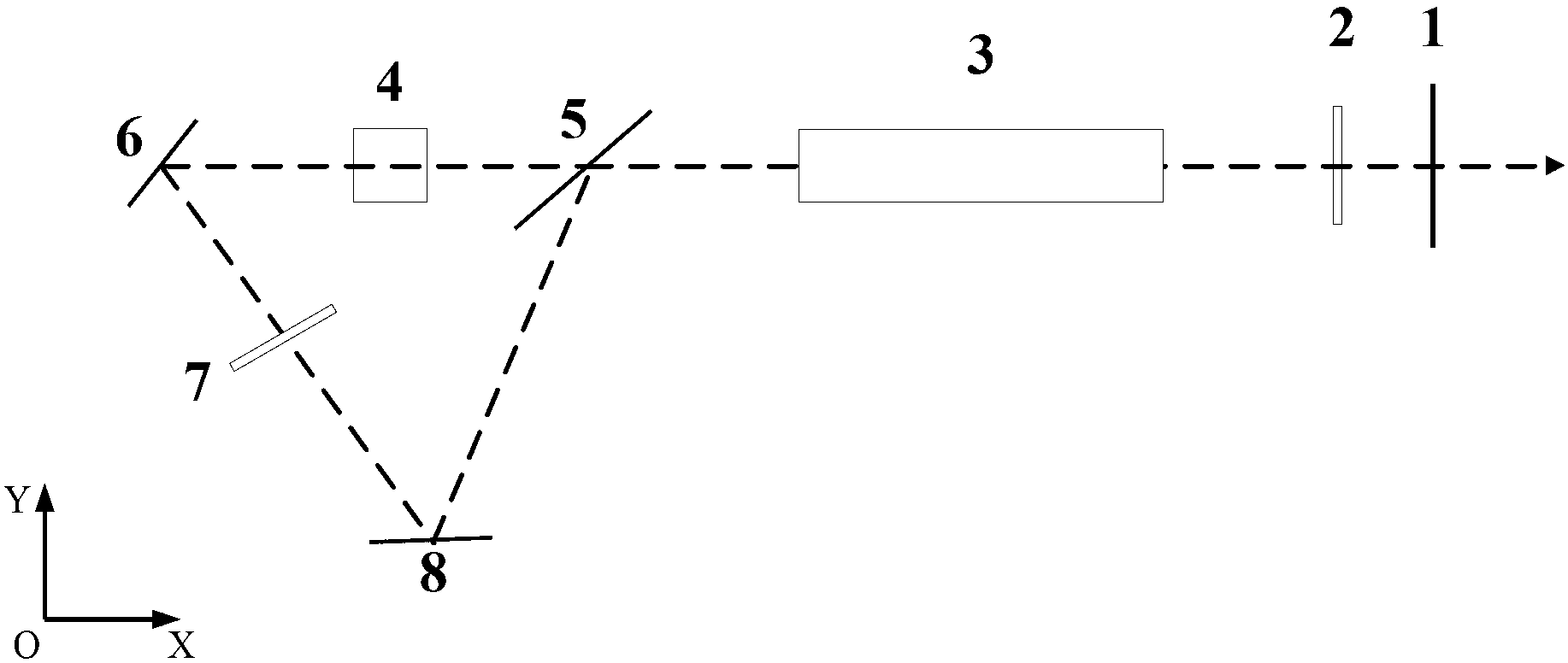
[0037] image 3 The second application example of the laser of the present invention under Q-switched operation is given, such as image 3 As shown, the laser includes a laser output mirror 1, a λ / 4 wave plate 2, a laser gain medium 3, a Q-switching device 4, a polarizing beam splitter 5, a first reflector 6, a λ / 2 wave plate 7, and a second reflector Mirror 8. Wherein the laser output mirror 1, the polarization beam splitter mirror 5, the first mirror 6, and the second mirror 8 constitute a laser resonant cavity. The optical path between the laser beam splitter 5 and the laser output 1 is the main optical path of the resonant cavity.

[0038] The laser output mirror 1 is a semi-transparent and half-reflective mirror, which realizes laser output while improving sufficient reflection and amplification of the resonant cavity.

[0039] The λ / 4 wave plate 2 is located on the main optical path of the laser resonator, and controls the ratio and composition of the polarization sta...


PUM


Abstract

The invention discloses a solid laser with annular polarization compensation. The solid laser with the annular polarization compensation comprises a laser output mirror, a lambda / 4 wave plate, a laser gain medium, a polarizing beam splitter, a first reflecting mirror, a lambda / 2 wave plate and a second reflecting mirror, wherein laser in a resonant cavity is split by the polarizing beam splitter into polarization-state orthogonal light beams, i.e. laser p and laser s; after being transmitted in an annular closed light path, two beams of laser return to the polarizing beam splitter and then are coupled into a main oscillation light path; and therefore, the compensated depolarized loss contributes to obtaining laser output with high average power, high peak power and high light beam quality. According to the solid laser with the annular polarization compensation, the closed transmission and the compensation of orthogonal polarized light are realized through a polarizing beam splitting principle and a wave plate rotation technique; by the adoption of Q-switching control on the coupling main oscillation light path, when the high-efficiency operation is realized, the polarization output of the laser is obtained; the controllable polarization-state laser output is realized by rotating the azimuth angle of the wave plate; and an annular polarization compensation method enables the length of the laser resonant cavity to be effectively compressed, so that a higher electronic-to-optical conversion efficiency can be obtained.

Description

technical field [0001] The invention relates to the field of lasers, in particular to a circular polarization-compensated solid-state laser. It is suitable for laser industrial processing and scientific research applications. Background technique [0002] Obtaining output of polarized light or green light with high average power, high peak power, and high beam quality has always been a hot issue in the field of laser development. The common technical problem is to obtain linearly polarized light with high beam quality and low loss in the resonator. In order to achieve the above goals, polarizing elements (Brewster plates, Glan prisms, film polarizers, etc.) are usually added to the resonator. ) to obtain polarized laser output, and then place the frequency doubling device inside the resonator (intra-cavity frequency doubling technology) or outside (extra-cavity frequency doubling technology) to achieve high-efficiency green light output. However, when the above device is a...

Claims


Application Information

Patent Timeline
Patent Type & Authority Applications(China)
IPC IPC(8): H01S3/117H01S3/10H01S3/08
Inventor 朱广志许昌云王文军朱晓郭飞
Owner WUHAN MEIMAN TECH
Why Eureka
Try Eureka