Over-current protection circuit for switch power supply

An overcurrent protection circuit, switching power supply technology, applied in emergency protection circuit devices, protection against overcurrent, electrical components, etc., can solve the problems of output voltage fluctuation, excessive current, etc. Overcurrent problem, the effect of protection from being burned

Active Publication Date: 2013-09-18
SHANGHAI HUAHONG INTEGRATED CIRCUIT
View PDF4 Cites 5 Cited by
  • Summary
  • Abstract
  • Description
  • Claims
  • Application Information

AI Technical Summary

Problems solved by technology

Although this overcurrent protection circuit can ensure that the current is limited within a reasonable range in each working cycle, it does not fundamentally solve the problem of excessive current, and directly turning off the PMOS switch interrupts the control loop, making the output voltage There are large fluctuations

Method used


Image

  • Over-current protection circuit for switch power supply
  • Over-current protection circuit for switch power supply
  • Over-current protection circuit for switch power supply

Examples


Embodiment Construction

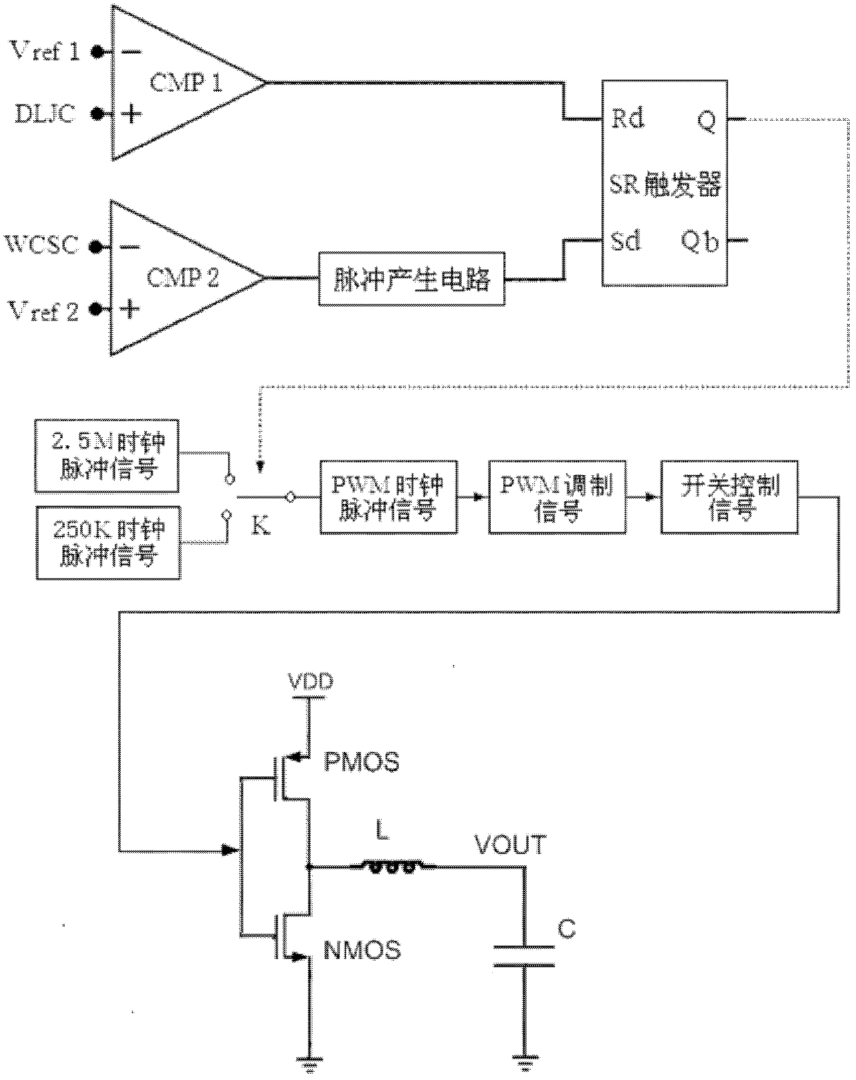
[0015] see image 3 As shown, in an embodiment of the present invention, the overcurrent protection circuit of the switching power supply includes: a first comparator CMP1, a second comparator CMP2, a pulse generating circuit and an SR flip-flop.

[0016] The inverting input terminal of the first comparator CMP1 is input with the first reference voltage Vref1 , and the non-inverting input terminal is input with the current detection voltage signal DLJC.

[0017] The inverting input of the second comparator CMP2 is input with the error amplifier output voltage signal WCSC, and the non-inverting input is input with the second reference voltage Vref2.

[0018] The input terminal of the pulse generating circuit is connected to the output terminal of the second comparator CMP2, and is used to change the rising edge of the output signal of the second comparator into a short pulse signal.

[0019] In the SR flip-flop, its reset terminal Rd is connected to the output terminal of the ...


PUM


Abstract

The invention discloses an over-current protection circuit for a switch power supply. The over-current protection circuit comprises: a first comparator which is for comparing a current detection voltage of the switch power supply with a first reference voltage and outputting a high level or a low level based on the comparison result; a second comparator which is for comparing an error amplifier output voltage of the switch power supply with a second reference voltage and outputting a high level or a low level based on the comparison result; a pulse generation circuit which is for hopping a rising edge of an output signal of the second comparator into a short-pulse signal; and an SR trigger which is for controlling a frequency gating switch to gate a corresponding working frequency signal based on the output of the first comparator and the pulse generation circuit. With the over-current protection circuit, problem that switch power supply chips are burned out due to the over-current is prevented, reliability of the switch power supply is improved and a stable voltage output can be obtained.

Description

technical field [0001] The invention relates to the field of switching power supplies, in particular to an overcurrent protection circuit of a switching power supply. Background technique [0002] DC / DC (direct current / direct current) switching power supply has the advantages of high efficiency and wide voltage range, and has been widely used in portable electronic equipment and green lighting and other fields. figure 1 It is the topology of BUCK (step-down) switching power supply. Through the alternate turn-on and turn-off of PMOS switch tube and NMOS switch tube, the inductor L and capacitor C are charged and discharged, thereby transferring energy from the input terminal to the output terminal VOUT. The switching power supply obtains the switching control signal through the PWM (pulse width modulation) modulation signal, thereby controlling the PMOS switching tube and the NMOS switching tube. Due to the complex application environment of the switching power supply, the l...

Claims


Application Information

Patent Timeline
Patent Type & Authority Applications(China)
IPC IPC(8): H02H7/10H02H3/08
Inventor 葛佳乐
Owner SHANGHAI HUAHONG INTEGRATED CIRCUIT
Why Eureka
Try Eureka