Power system cascading failure simulation method based on unified power flow controller

A power flow controller and power system technology, which is applied in the direction of AC network circuits, instruments, electrical components, etc., can solve the inconsistency of operating conditions, cannot effectively avoid large-scale power outages in the power system, and cascading faults cannot truly reflect the cascading fault propagation process, etc. question

Active Publication Date: 2015-04-15
CHONGQING UNIV
View PDF3 Cites 0 Cited by
  • Summary
  • Abstract
  • Description
  • Claims
  • Application Information

AI Technical Summary

Problems solved by technology

The main disadvantages of this method are: ①Using electrical betweenness to judge the importance of nodes ignores factors such as the size, direction and reactive voltage of the actual power supply in the power system, which cannot reflect the actual operation of the power system; ②In cascading faults During the simulation process, the adjustment method of the line parameters to alleviate the further occurrence of cascading faults adopts the assumption that the line parameters of each circuit can be adjusted proportionally, which is inconsistent with the actual system operation; ③ Although it is mentioned in the paper that flexible AC transmission (FACTS) components to adjust the parameters of related lines is only a theoretical assumption without a specific implementation process, and flexible AC transmission (FACTS) components are installed on each transmission line of the power system, which is difficult to achieve in practice; ④ When adjusting line parameters, there is no Considering the system security constraints, it cannot reflect the actual operation status of the power system after a fault
Therefore, using this method to simulate cascading faults in the power system cannot truly reflect the propagation process of cascading faults, thus cannot provide a basis for the safety and reliability protection of the power system, and cannot effectively avoid the occurrence of large-scale power outages in the power system

Method used


Image

  • Power system cascading failure simulation method based on unified power flow controller
  • Power system cascading failure simulation method based on unified power flow controller
  • Power system cascading failure simulation method based on unified power flow controller

Examples


Embodiment

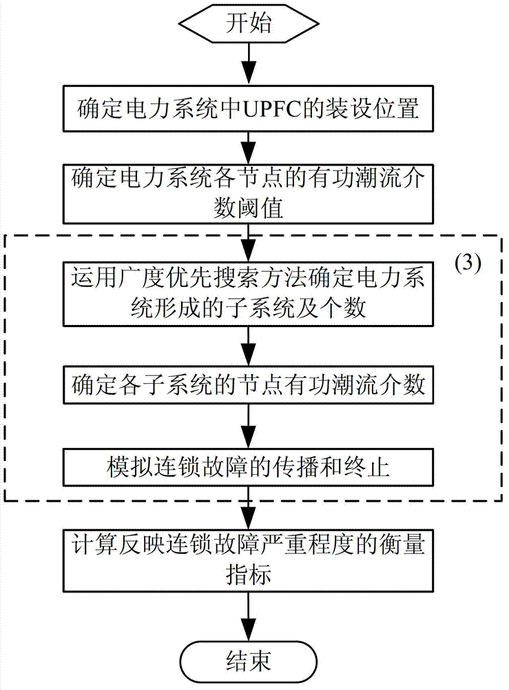
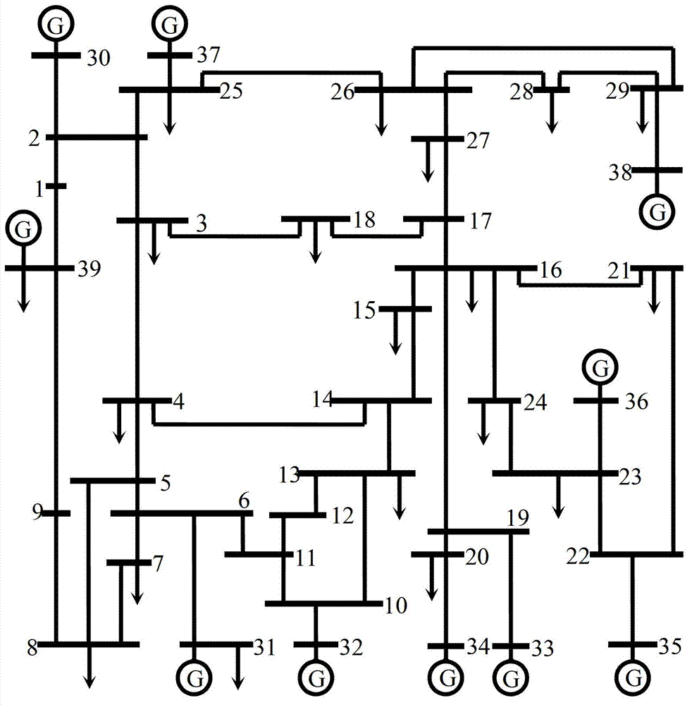
[0102] like figure 1 , 2 As shown, the specific steps of a power system cascading failure simulation method based on the unified power flow controller are as follows:

[0103] (1) Determine the installation location of UPFC in the power system

[0104] 1) Input basic parameters

[0105] First, the basic parameters of the power system and the basic parameters of the unified power flow controller (UPFC) are input. The basic parameters of the power system include node number (1, 2, ..., 39), node type, node corresponding voltage level, active load of each node (P L ) and reactive load (Q L ), the number of nodes connected to generators, the active power output by each generator (P G ) and reactive power (Q G ), the node numbers at the beginning and end of each line, the line resistance (R), line reactance (X) and line susceptance (B), the rated voltage of the line (U B ), reference power (S B ), the operating coefficient (α=1.5) of the node, the limit coefficient (β=3) of...


PUM


Abstract

The invention provides a power system cascading failure simulation method based on a unified power flow controller and belongs to the technical field of power system security and reliability protection. A computer is used for determining the installation position of the unified power flow controller in a power system firstly, determining an active power flow betweenness threshold value of each node of the power system, performing power system cascading failure simulation based on the unified power flow controller and finally calculating measurement index for reflecting severity of cascading failure through procedures. The power system cascading failure simulation method gives consideration to power flow directivity and the operation mode of the system, optimizes the installation position for installing the unified power flow controller, effectively performs line parameter regulation while meeting safe operation constraints of the power system, and can reflect the propagation process of the cascading failure of the power system actually. The power system cascading failure simulation method based on the unified power flow controller can be widely applied to the cascading failure simulation of the power system, is particularly suitable for the cascading failure simulation of a large-scale complicated power system, and provides a scientific basis for preventing occurrence of the cascading failure of the power system.

Description

technical field [0001] The invention belongs to the technical field of power system safety and reliability protection, and in particular relates to a power system cascading fault simulation method based on a unified power flow controller. Background technique [0002] With the development of the economy and the increase of power demand, the scale of the power system continues to expand and the structure becomes more and more complex, and the safety and reliability of the power system operation are more and more highly valued by people. In recent years, power system blackouts caused by partial fault propagation have occurred frequently. The statistical analysis of these power system blackouts shows that most of the blackouts are caused by cascading faults. Cascading faults in the power system refer to the fact that after some equipment in the power system has an accidental failure, the power flow of the power system will be transferred. affect the entire power system. The c...

Claims


Application Information

Patent Timeline
Patent Type & Authority Patents(China)
IPC IPC(8): H02J3/00G06F17/50
CPCY02T10/82
Inventor 王韶董光德刘沛铮王理丽恭秀芬张煜成张知朱姜峰
Owner CHONGQING UNIV
Why Eureka
Try Eureka