
Control method and control system for grid-side converter

A grid-side converter and shaft current technology, applied in the field of power electronics, can solve the problems of grid-side converter runaway danger, converter batch failure off-grid grid, DC side overvoltage or overcurrent, etc.

Active Publication Date: 2013-09-18
SUNGROW POWER SUPPLY CO LTD
View PDF3 Cites 18 Cited by
  • Summary
  • Abstract
  • Description
  • Claims
  • Application Information

AI Technical Summary

Problems solved by technology

During the working stage of the converter, when the grid voltage rises transiently, the control margin of the DC side decreases, resulting in the risk of runaway of the grid-side converter. If the grid-side converter loses control, it will easily lead to overvoltage or overcurrent on the DC side , so that the converter cannot run stably on the grid, and even fails to be disconnected from the grid
And with the continuous increase of the installed capacity of generators, the frequency of grid voltage transient rise will increase, and the serious impact of the resulting batch failure of converters on the grid will become increasingly prominent

Method used


Image

  • Control method and control system for grid-side converter
  • Control method and control system for grid-side converter
  • Control method and control system for grid-side converter

Examples


specific Embodiment

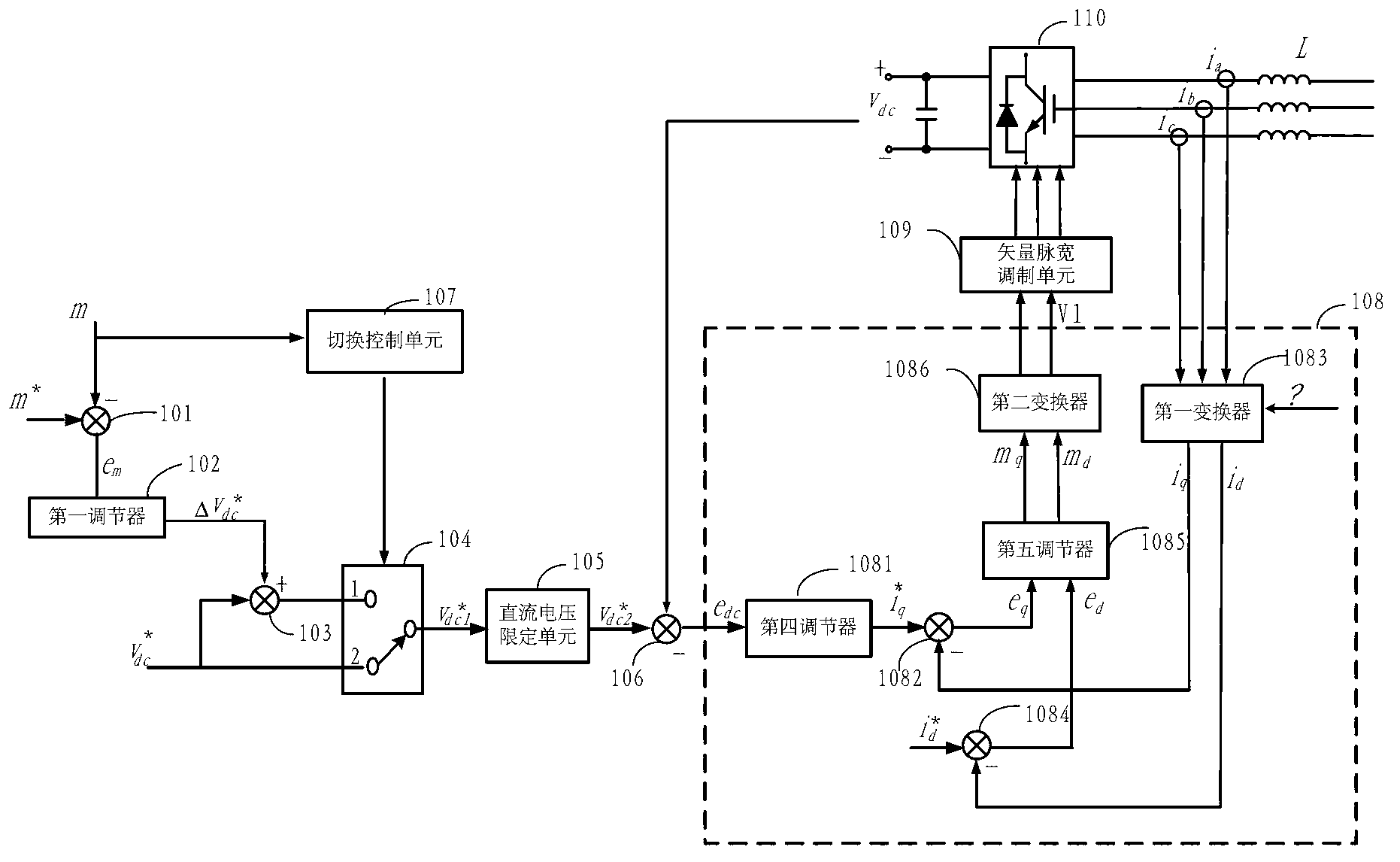
[0121] see Figure 7 , the present invention also provides a specific embodiment of a grid-side converter control method, the method comprising:

[0122] S701: When the modulation ratio is in the first setting interval, the power grid voltage value is normal at this time, execute S702; when the modulation ratio is in the second setting interval, the grid voltage has a transient increase, and execute S703.

[0123] S702: Set the DC bus voltage reference value Vdc * It is limited within the limited range of the DC voltage, and then S704 is executed.

[0124] S703: increase the voltage by ΔVdc * and DC bus voltage reference value Vdc * The sum is limited within the limited range of the DC voltage, and then S704 is executed.

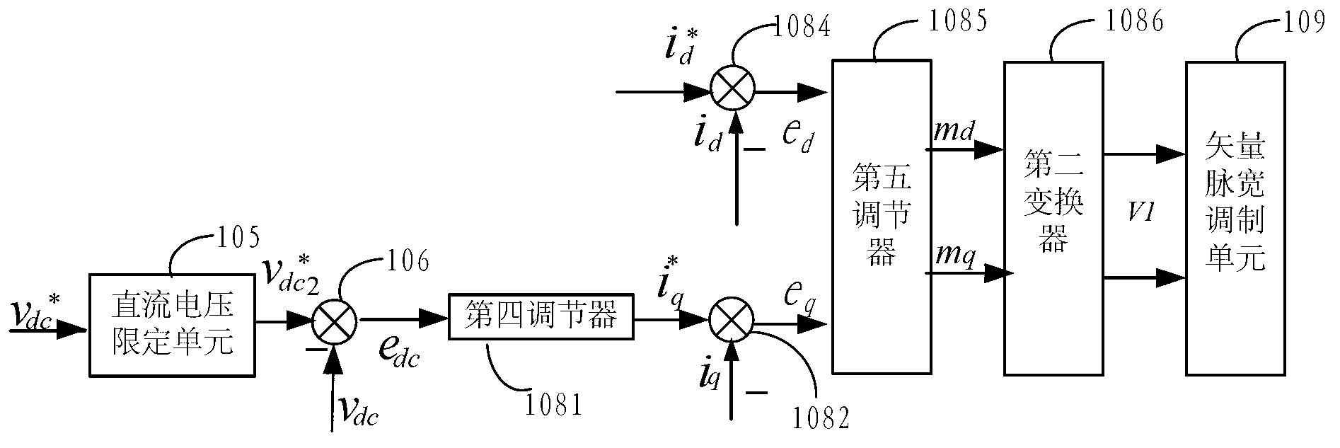
[0125] S704: Use the limited voltage as the given value of the DC bus voltage, and according to the given value and the DC bus voltage Vdc * The difference value generates the q-axis current given value i in the two-phase rotating coordinate system q ...


PUM


Abstract

The invention provides a control method and a control system for a grid-side converter. The method includes: when a modulation ratio is at a first set section, a direct-current bus voltage reference value is limited in a direct-current limit range, when the modulation ratio is at a second set section, the sum of a voltage increment and the direct-current bus voltage reference value is limited in the direct-current limit range; the limited voltage is used as a given value of direct-current bus voltage; the modulation ratio is obtained according to reference voltage and the direct-current bus voltage of a vector pulse width modulation unit. The modulation ratio can reflect voltage values of a power grid, when the modulation ratio is at the first set section, power grid voltage is normal, when the modulation ratio is at the second set section, the power grid voltage is in transient increase, so that the given value of the direct-current voltage is increased, saturation of the modulation ratio is restrained, controllability of the grid-side converter is increased, stable grid-connected operation of the grid-side converter during transient voltage increase is guaranteed, and high-voltage ride through capability of the converter is increased.

Description

technical field [0001] The invention relates to the field of power electronics, in particular to a control method and system for a grid-side converter. Background technique [0002] Converters include machine-side converters and grid-side converters, etc. The machine-side converters, namely rectifiers, are connected to generators, the grid-side converters, namely inverters, are connected to the grid side, and the machine-side converters The converter and the grid-side converter are connected to a DC bus for rectification and inverter control. During the working stage of the converter, when the grid voltage rises transiently, the control margin of the DC side decreases, resulting in the risk of runaway of the grid-side converter. If the grid-side converter loses control, it will easily lead to overvoltage or overcurrent on the DC side , so that the converter cannot be stably connected to the grid, and even fails to be disconnected from the grid. And as the installed capacit...

Claims


Application Information

Patent Timeline
IPC IPC(8): H02J3/38
Inventor 曹仁贤张兴屠运武谢震汪令祥杨淑英吴玉杨梁信信
Owner SUNGROW POWER SUPPLY CO LTD
Learn More