
Flat vibration motor

A technology of flat vibrating motors and magnets, which is applied in the direction of electric components, mechanical energy control, electrical components, etc. It can solve the problems of slow motor feedback to signals, affecting the service life of the motor, and poor user experience, so as to achieve fast startup and easy assembly. , The effect of signal feedback sensitivity

Inactive Publication Date: 2013-09-18
FORYOU MULTIMEDIA ELECTRONICS +1
View PDF10 Cites 3 Cited by
  • Summary
  • Abstract
  • Description
  • Claims
  • Application Information

AI Technical Summary

Problems solved by technology

However, the force between the coil and the magnet of the flat vibrating motor with this structure is limited. When the motor is started, a higher current is required, the power consumption of the motor is larger, and the high current is also more damaging to the motor, affecting the service life of the motor and The feedback of the motor to the signal is slowed down, and the use feeling is not good

Method used


Image

  • Flat vibration motor
  • Flat vibration motor
  • Flat vibration motor

Examples


Embodiment Construction

[0028] In order to facilitate the understanding of those skilled in the art, the present invention will be further described in detail below in conjunction with the accompanying drawings and embodiments:

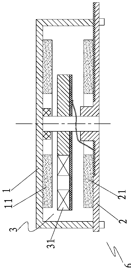
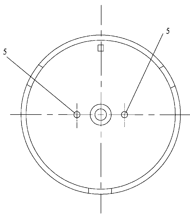
[0029] Details are attached Figure 2-5 shown. The flat vibration motor disclosed in this embodiment also includes an upper shell 1, a lower shell 2, and an eccentric rotor 3 installed in the cavity formed by the upper shell 1 and the lower shell 2. The eccentric rotor 3 is provided with two coils 31 and The counterweight plate, the two coils 31 and the counterweight plate are located in the same semicircle arc of the eccentric rotor 3. When the eccentric rotor 3 rotates, since the center of gravity is not at the center of rotation, vibrations are generated. One of the biggest differences between this scheme and the existing flat vibration motor is that there are many pairs of upper magnets 11 and lower magnets 21 symmetrically arranged on the inner wall of the upper shell ...


PUM


Abstract

The invention discloses a flat vibration motor. The flat vibration motor comprises an upper casing, a lower casing and an eccentric rotor which is arranged in a cavity which is formed by the upper casing and the lower casing. A coil is arranged on the eccentric rotor. Pairs of upper magnet and lower magnet are symmetrically arranged on the inner wall of the upper casing and the inner wall of the lower casing. The magnetic lines of each pair of upper magnet and lower magnet in the cavity form a closed magnetic circuit. The eccentric rotor is located in a magnetic field formed by the upper magnets and the lower magnets. The flat vibration motor provided by the invention has the advantages that the magnets are arranged in the upper casing and the lower casing, thus magnetic leakage in the motor is reduced; the magnetic lines between the upper magnets and the lower magnets are intense; a large magnetic flux is acquired; the coil can acquire a great driving force; the current required by the motor is small, and the energy consumption is low; the service life of the motor is long; the starting of the eccentric rotor is fast; signal feeding back of the motor is sensitive; by arranging a joint structure, the assembly of the motor is easy; and improvement can be directly carried out on the existing motor, which is convenient for improvement and the application of a customer.

Description

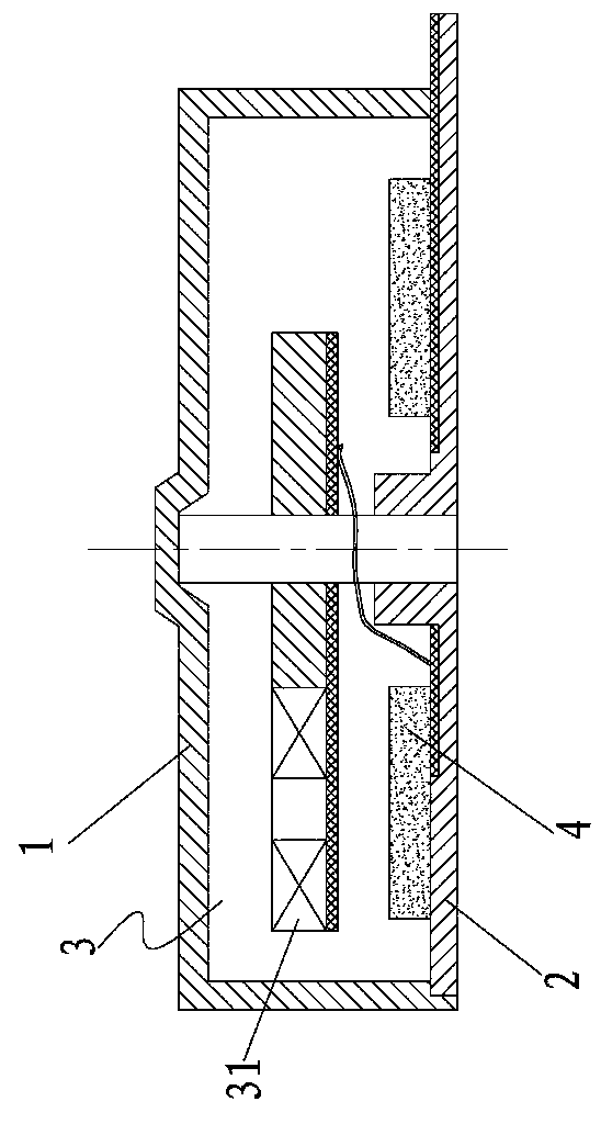
technical field [0001] The invention relates to an improved technology of a flat vibrating motor. Background technique [0002] Existing mobile phones are all powered by batteries. In order to increase the use time of mobile phones, it is very important to reduce the energy consumption of each electronic component in the mobile phone. as attached figure 1 Shown is a schematic diagram of the structure of most existing flat vibration motors for mobile phones, the flat motor upper shell 1, lower shell 2 and the eccentric rotor 3 installed in the cavity formed by the upper shell and the lower shell, the eccentric rotor is provided with The coil 31 is provided with magnets 4 uniformly distributed along the rotation direction of the eccentric rotor on the inner wall of the lower case. When energized, the magnetic field generated by the current in the coil interacts with the magnetic field of the magnet to keep the rotor spinning. However, the force between the coil and the magn...

Claims


Application Information

Patent Timeline
Patent Type & Authority Applications(China)
IPC IPC(8): H02K7/075
Inventor 李德烈郑邹鹰杜军南青吉曾珍平张所凯
Owner FORYOU MULTIMEDIA ELECTRONICS
Learn More