Driving mechanism for gas blowing cover of core-making machine

A technology of driving mechanism and blowing hood, which is applied in the direction of cores, molding machines, manufacturing tools, etc., can solve the problems of large space required for equipment layout, impact, and high structural cost, so as to achieve no impact in place, reduce rotation speed, The effect of long service life

Active Publication Date: 2015-07-01
SUZHOU MINGZHI TECH
View PDF9 Cites 0 Cited by
  • Summary
  • Abstract
  • Description
  • Claims
  • Application Information

AI Technical Summary

Problems solved by technology

This drive mechanism takes up a lot of space, which requires more space for equipment layout
In addition, if the air cylinder drive mode is adopted, the drive cylinder will not decelerate when the blowing cover is in place, and impact will occur; if the hydraulic cylinder drive mode is adopted, the hydraulic valve can be used to control the flow and pressure to meet the stability requirements, but this structure is costly and difficult to control. complex

Method used


Image

  • Driving mechanism for gas blowing cover of core-making machine
  • Driving mechanism for gas blowing cover of core-making machine

Examples


Embodiment 1

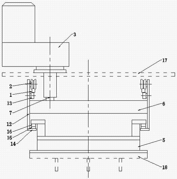
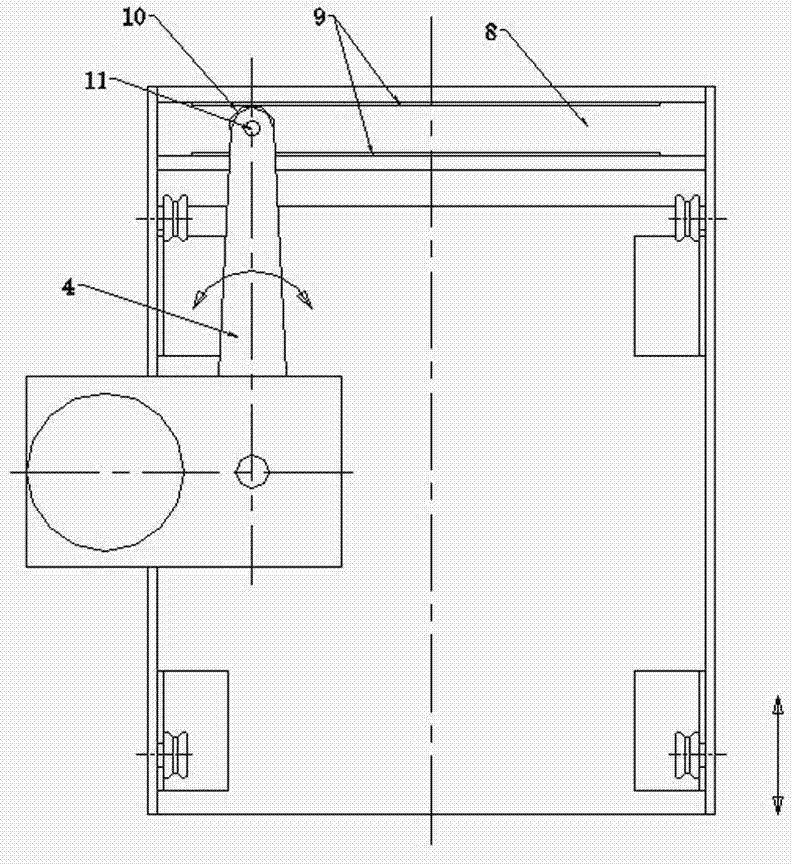
[0027] Embodiment one: see attached figure 1 And attached figure 2 As shown, a blowing hood driving mechanism of a core making machine is composed of a driving device and a guiding device. The guiding device includes a pair of guide rails 1 arranged in parallel along the moving direction of the blowing hood 5 and guide wheels matched with the guide rails. , the driving device includes a geared motor 3 installed on the upper frame of the core making machine, a swing arm 4 fixedly connected to the output shaft of the geared motor 3 at one end via a connecting shaft 7, and a blowing trolley 6 connected to the blowing cover 5; The output shaft of the reduction motor 3 is vertically arranged, and one end of the blowing trolley 6 is provided with a guide groove 8 arranged perpendicularly to the direction of the guide rail 1, and the guide groove 8 is formed by a pair of guide plates 9 arranged in parallel, and the swing arm 4 is arranged in parallel. One end is rotatably connected...

Embodiment 2

[0032] Embodiment 2: A blowing hood driving mechanism of a core making machine, the basic structure of which is the same as that of Embodiment 1, wherein the rotating power output mechanism is a rotating hydraulic cylinder or a hydraulic motor. In this embodiment, since the rotary power output mechanism adopts a hydraulic mechanism, the hydraulic oil output of the ready-made hydraulic station of the core making machine can be used for output, and no additional power source is needed, which is easy to implement.


PUM


Abstract

The invention discloses a driving mechanism for a gas blowing cover of a core-making machine. The mechanism is composed of a driving device and a guiding device, wherein the guiding device comprises a pair of guide rails which are arranged in parallel along a motion direction of the gas blowing cover and guiding wheels matched with the guiding rails; the device is characterized in that the driving device comprises a rotational power outputting mechanism, a swinging arm and a gas blowing trolley; an output shaft of the rotational power outputting mechanism is vertically arranged; a guiding groove perpendicular to the directions of the guide rails is formed in one end of the gas blowing trolley; a roller is rotatably connected with the swinging arm and is positioned in the guiding groove and is in contact with the guiding groove in a rolling mode to be limited; the guide rails are linear guide rails of which the tops of the cross sections are in an inverted V shape; the guiding wheels are V-shaped wheels matched with the tops of the guide rails. According to the driving mechanism, surplus arrangement spaces are not needed to be occupied; by reducing rotation speed, speed reduction in place is realized, the mechanism is in place stably without impact, the controlling mode is simple, a guiding structure is simple and the service life is long.

Description

technical field [0001] The invention relates to a component of metal casting equipment, in particular to a driving mechanism of a blowing hood of a core making machine. Background technique [0002] The blowing hood is an important part of the cold box core making machine, and the blowing plate is fixed at the lower part of the blowing hood. During the production process of the core making machine, the core box and the shooting plate are tightly sealed for sand shooting, and the core box and the air blowing plate are tightly sealed for blowing and curing to complete core making. [0003] For fixed shot core making machines, the blowing plate needs to move back and forth or left and right. When shooting sand, the blowing plate is outside the nozzle; when blowing, move the blowing board to the lower part of the nozzle for blowing and curing; after the blowing is completed, the blowing board moves out of the nozzle. For the mobile shooter core making machine, the air blowing ...

Claims


Application Information

Patent Timeline
Patent Type & Authority Patents(China)
IPC IPC(8): B22C9/10B22C15/23
Inventor 王鼎铭王直良
Owner SUZHOU MINGZHI TECH
Why Eureka
Try Eureka