
Integrated electronic hydraulic brake system

An integrated electronic and hydraulic braking technology, applied in the direction of hydraulic brake transmission, brake, brake transmission, etc., can solve the problems of increasing the introduction of foreign substances and reducing durability, so as to improve fuel efficiency and durability , The effect of convenient assembly operation

Inactive Publication Date: 2013-09-25
HL MANDO CORP
View PDF12 Cites 14 Cited by
  • Summary
  • Abstract
  • Description
  • Claims
  • Application Information

AI Technical Summary

Problems solved by technology

Therefore, the movement of the piston causes friction, and long-term use of the pedal simulator reduces durability and increases the possibility of bringing in foreign matter

Method used


Image

  • Integrated electronic hydraulic brake system
  • Integrated electronic hydraulic brake system
  • Integrated electronic hydraulic brake system

Examples


Embodiment Construction

[0034] Embodiments of the present invention will now be described in detail, examples of which are illustrated in the accompanying drawings, wherein like reference numerals refer to like parts throughout.

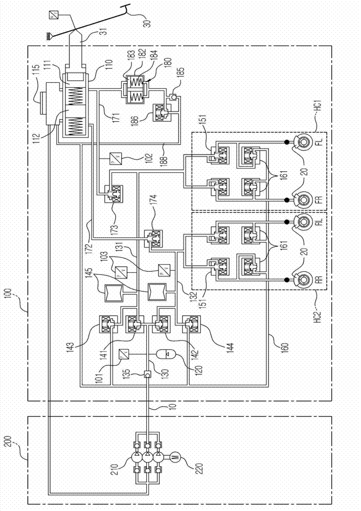
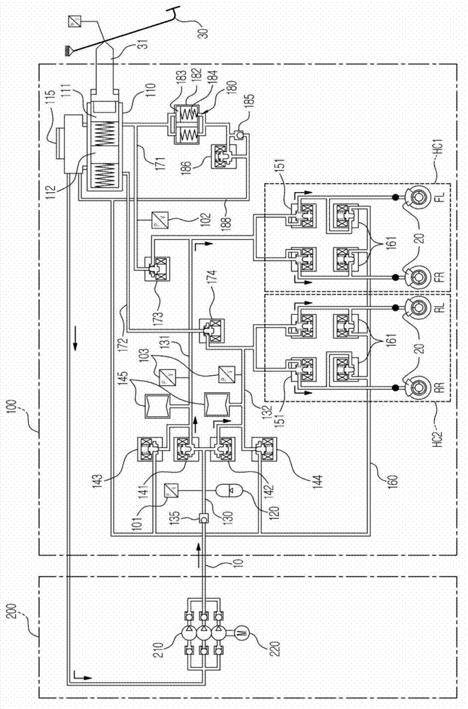
[0035] figure 2 is a hydraulic circuit diagram of an integrated electro-hydraulic braking system according to an embodiment of the present invention.

[0036] The integrated electro-hydraulic braking system according to an embodiment of the present invention is mainly divided into two units. refer to figure 2, the integrated electronic hydraulic braking system includes an integrated hydraulic control device 100 and a power source unit 200; the integrated hydraulic control device 100 includes a brake pedal 30 operated by the driver during a braking operation, and force is transmitted from the brake pedal 30 to it The master cylinder 110, the oil reservoir 115 connected to the upper part of the master cylinder 110 to store oil, each of which is connected to two hydraulic ...


PUM


Abstract

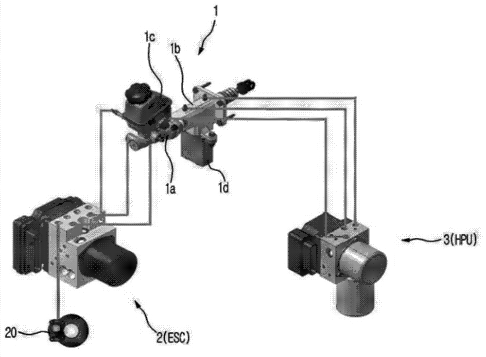
An integrated electronic hydraulic brake system provided with an actuator including a master cylinder and a pedal simulator, an electronic stability control (ESC) and a hydraulic power unit (HPU) in a single unit.

Description

technical field [0001] Embodiments of the present invention relate to an electro-hydraulic braking system, and more particularly, to an integrated electro-hydraulic braking system including an actuator, an electronic stability controller (ESC), and a hydraulic power unit (HPU), The actuator has a master cylinder and a pedal simulator, and the actuator, electronic stability controller, and hydraulic power unit are configured as a single unit. Background technique [0002] In recent years, in order to improve fuel efficiency and reduce exhaust gas, hybrid vehicles, fuel cell vehicles, and electric vehicles have been actively developed. These vehicles need to be provided with a braking device, ie a braking device for the vehicle braking system. A braking device for a vehicle refers to a device configured to slow down or stop the vehicle while the vehicle is being driven. [0003] In general, braking devices include vacuum brakes that generate braking force by using suction pr...

Claims


Application Information

Patent Timeline
Patent Type & Authority Applications(China)
IPC IPC(8): B60T13/66
CPCB60T8/368B60T8/4081B60T11/24B60T8/17B60T13/12B60W10/18B60T13/142B60T13/58B60T13/686
Inventor 金贤俊
Owner HL MANDO CORP
Learn More