Fuel oil evaporation system and motorcycle thereof

A fuel evaporation system, motorcycle technology, applied in the direction of charging system, engine components, machine/engine, etc., can solve the problems of complicated connection process, deformation and bending of ventilation pipes, blockage, etc., to simplify installation procedures and reduce installation space , The effect of simplifying the installation structure

Active Publication Date: 2011-11-02
广东隆鑫机车有限公司
View PDF8 Cites 2 Cited by
  • Summary
  • Abstract
  • Description
  • Claims
  • Application Information

AI Technical Summary

Problems solved by technology

In the prior art, the activated carbon tank and the pipeline system are installed on the vehicle frame at the lower part of the fuel tank, and the activated carbon tank is connected to the gas phase of the oil-gas separator in the fuel tank through the fuel vapor pipe. Therefore, the pipeline system needs to be installed before installing the fuel tank. It is connected with activated carbon tank, dump valve and one-way valve. The connection process is extremely complicated. It is necessary to hold up the fuel tank and then connect the pipeline. Since the fuel tank is lifted and connected to the pipeline, placing it on the frame will cause some problems such as deformation and bending of the vent pipe, which will cause blockage.

Method used


Image

  • Fuel oil evaporation system and motorcycle thereof
  • Fuel oil evaporation system and motorcycle thereof
  • Fuel oil evaporation system and motorcycle thereof

Examples


Embodiment Construction

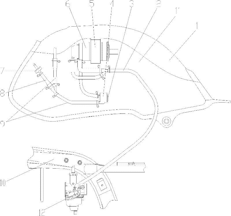
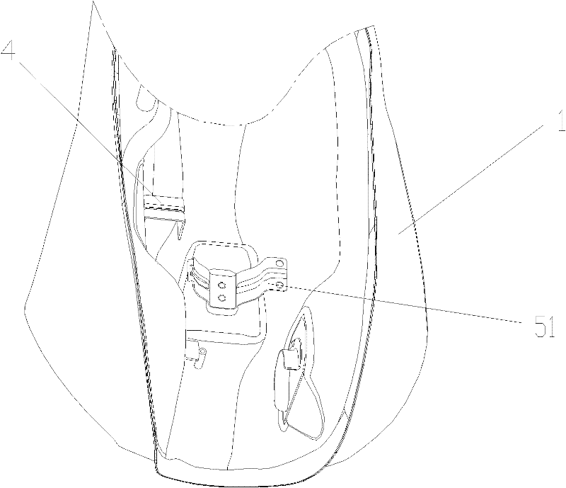
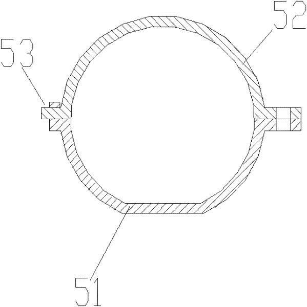
[0021] figure 1 It is a structural schematic diagram of the present invention, figure 2 is the bottom view of the fuel tank, image 3 It is a schematic diagram of the structure of the canister mounting bracket, Figure 4 It is a schematic diagram of the installation of the dump valve, as shown in the figure: the fuel evaporation system of this embodiment includes a carbon canister 6 and a pipeline system. The carbon canister 6 is fixed on the lower surface of the bottom plate of the fuel tank 1. Air pipe I 9 and air pipe II 2, one end of the air pipe I 9 communicates with the gas phase of the fuel tank oil-gas separator, and the other end communicates with the fuel vapor inlet of the charcoal tank 6, and the air pipe I 9 pipeline is provided with a dump valve 3, said The dump valve 3 is fixed on the lower surface of the bottom plate of the fuel tank 1, one end of the vent pipe II 9 is connected to the desorption port of the carbon tank 6, and the other end is connected to t...


PUM


Abstract

The invention relates to a fuel oil evaporation system and a motorcycle thereof, comprising a carbon jar and a pipeline system, wherein the carbon jar is fixedly arranged on the lower surface of the bottom plate of a fuel oil tank; the pipeline system comprises a breather pipe I and a breather pipe II; one end of the breather pipe I is communicated to the gas phase of the gas and oil separator ofthe fuel oil tank, and the other end is communicated to the fuel oil steam adsorption mouth of the carbon jar; the pipeline of the breather pipe I is provided with a dumping valve; the dumping valve is fixed on the lower surface of the bottom plate of the fuel oil tank; one end of the breather pipe II is communicated to the desorption mouth of the carbon jar; and the other end is communicated to the mixed gas inlet of a carburettor. The fuel oil evaporation system is integrally connected with the fuel oil tank. When the fuel oil evaporation system is assembled, the fuel oil tank can be firstly installed, and then, a pipeline between the carbon jar and the carburettor is connected, thereby saving labor force. Meanwhile, abnormal bending when a breathing line is installed can be avoided to guarantee that the breathing line is smooth so as to ensure that the fuel oil evaporation system can normally operate for a long period. The structural pipeline system has simple structure, workload for installation is reduced, the surface of the fuel oil tank and the periphery can be guaranteed to be beautiful and compact, and use and maintenance cost is lowered.

Description

technical field [0001] The invention relates to an auxiliary component for an engine, in particular to a fuel evaporation system component and a motorcycle thereof. Background technique [0002] Gasoline engine is the preferred energy source for light power equipment, and it is more commonly used in motorcycles. Gasoline is a volatile liquid. The fuel tank is often full of steam at room temperature. Under normal circumstances, the fuel tank is sealed to prevent oil vapor from polluting the environment or causing unnecessary safety accidents; and due to the existence of positive pressure of oil vapor in the fuel tank, It can also suppress the further evaporation of gasoline, but the fuel tank is not necessarily sealed or not permanently sealed, and in order to prevent the fuel vapor from volatilizing into the atmosphere, a fuel evaporation control system is used to introduce fuel vapor into combustion and prevent volatilization into the atmosphere. [0003] The fuel evaporat...

Claims


Application Information

Patent Timeline
Patent Type & Authority Applications(China)
IPC IPC(8): F02M25/08
Inventor 李小红覃永川
Owner 广东隆鑫机车有限公司
Why Eureka
Try Eureka