
Melt polycondensation reaction method, and reactor and falling film tube used for same

A polycondensation reactor and melt polycondensation technology, applied in chemical/physical/physical-chemical stationary reactors, chemical instruments and methods, thin-film liquid-gas reaction, etc. The problems of unfavorable adhesion and polycondensation process can be achieved to improve quality stability and uniformity, uniform reaction temperature and sufficient heat exchange.

Active Publication Date: 2014-06-04
ZHEJIANG SCI-TECH UNIV +1
View PDF4 Cites 0 Cited by
  • Summary
  • Abstract
  • Description
  • Claims
  • Application Information

AI Technical Summary

Problems solved by technology

This type of reactor is limited by the bridge of the melt network, and the disc or mesh must be kept at a large distance, resulting in a limited surface area of ​​the melt per unit volume; limited by the structure of the reactor, the reaction temperature is not uniform enough; the melt in the molten pool stays The time is long and affected by the static pressure head, which is unfavorable to the polycondensation process; the inside of the reactor depends on the liquid level difference of the molten pool to flow, the flow condition at the kettle wall is not good, and there are many dead zones; and due to the adhesion of a large amount of melt, the stirring shaft produces Quite winding, there is not much room for further improvement of equipment for viscosity increase
Especially for the preparation of high-viscosity melts, its excessive dead zone, entrainment, limited film formation and surface renewal, and severe degradation caused by excessive residence time limit the application of this type of reactor.

Method used


Image

  • Melt polycondensation reaction method, and reactor and falling film tube used for same
  • Melt polycondensation reaction method, and reactor and falling film tube used for same
  • Melt polycondensation reaction method, and reactor and falling film tube used for same

Examples


Embodiment 1

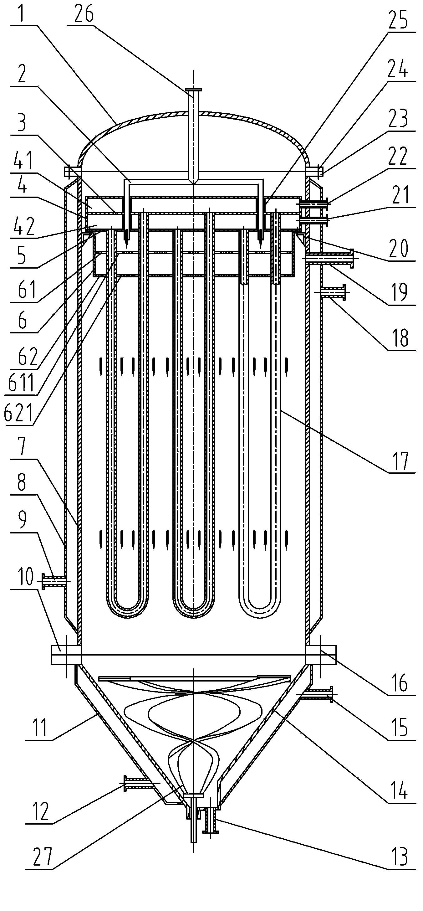
[0036] Embodiment 1, with reference to attached figure 1 .

[0037] In this embodiment, the U-shaped falling film tube is a round tube.

[0038] A kind of melting polycondensation reactor provided by the present embodiment, such as figure 1As shown, it includes: a vertical housing 7, a head 1 connected to the upper end of the vertical housing 7 and a bottom shell 14 at the lower end, the top of the head 1 is provided with a feed port 26, and the top of the vertical housing 7 is provided with Vacuum suction port 19, the bottom of the bottom shell 14 is provided with a discharge port 13, there are many vertically installed U-shaped falling film tubes 17 in the vertical shell 7, and an agitator 27 is installed below the U-shaped falling film tubes 17; The reactor has a heat transfer system, including: heat transfer medium inlet or outlet 22, upper box 41, U-shaped falling film tube 17, lower box 42, heat transfer medium outlet or inlet 21, upper box, U-shaped falling film The ...

Embodiment 2

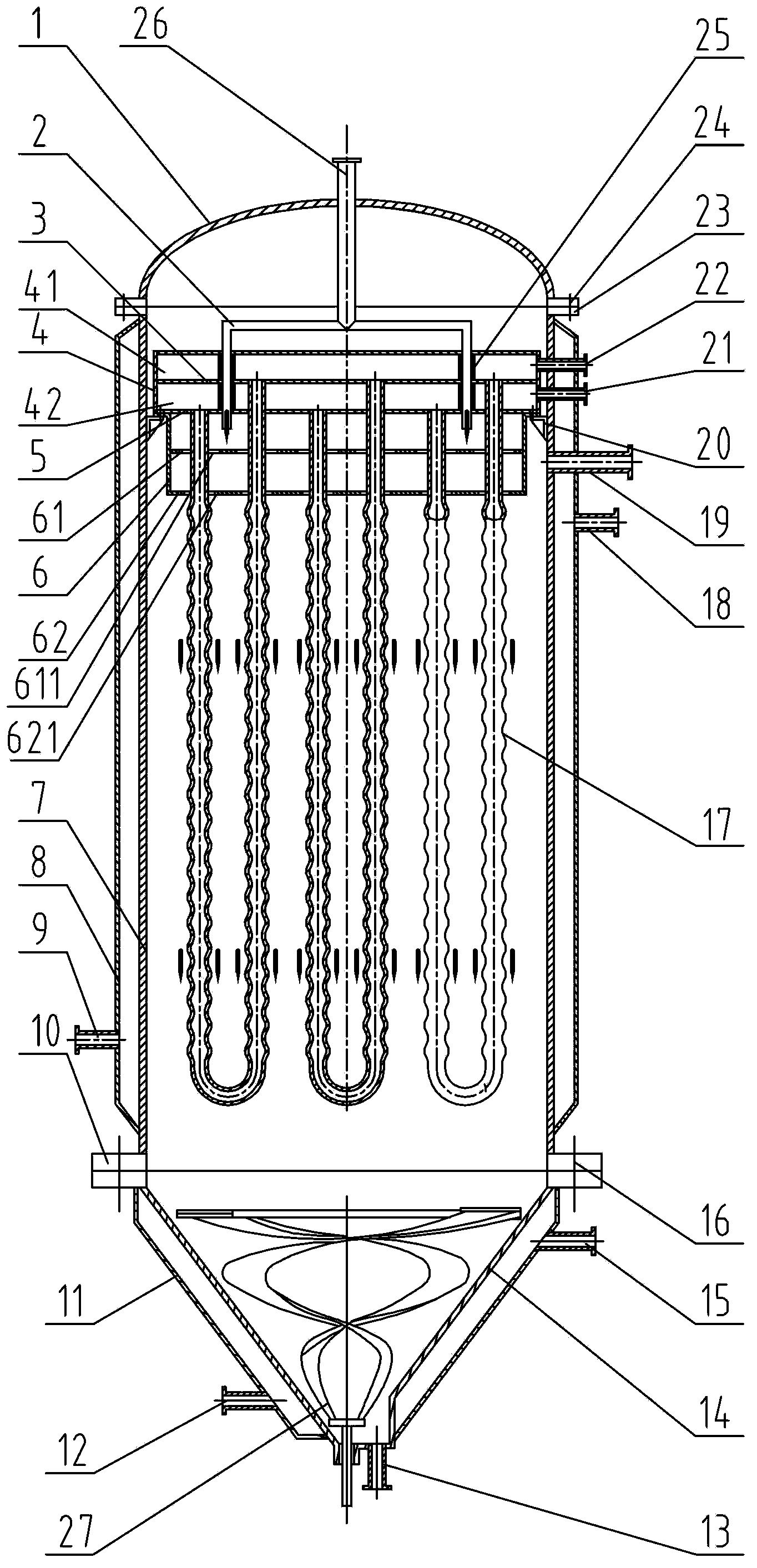
[0050] Embodiment 2, with reference to attached figure 2 , 4 , 5a, 5b, 5c, 5d.

[0051] In this embodiment, the straight part of the U-shaped falling film tube 17 is a corrugated tube or a corrugated tube.

[0052] Such as Figure 4 As shown, the corrugated tube is composed of arc sections and straight tube sections alternately, and the peak diameter D 2 and straight pipe diameter D 1 The difference and the arc segment length L 1 Ratio (D 2 -D 1 ) / L 1 =0.05~1.0.

[0053] Such as Figure 5a As shown, the bellows can be arc-shaped bellows, that is, the longitudinal tangent contour of the bellows is a continuous wave tangent to the large and small arcs.

[0054] Such as Figure 5b As shown, the bellows can be a scaling bellows, that is, the bellows is composed of expansion sections and contraction sections alternately.

[0055] Such as Figure 5c As shown, the bellows can choose the arc tangent type bellows, that is, the longitudinal tangent contour of the bellows i...

Embodiment 3

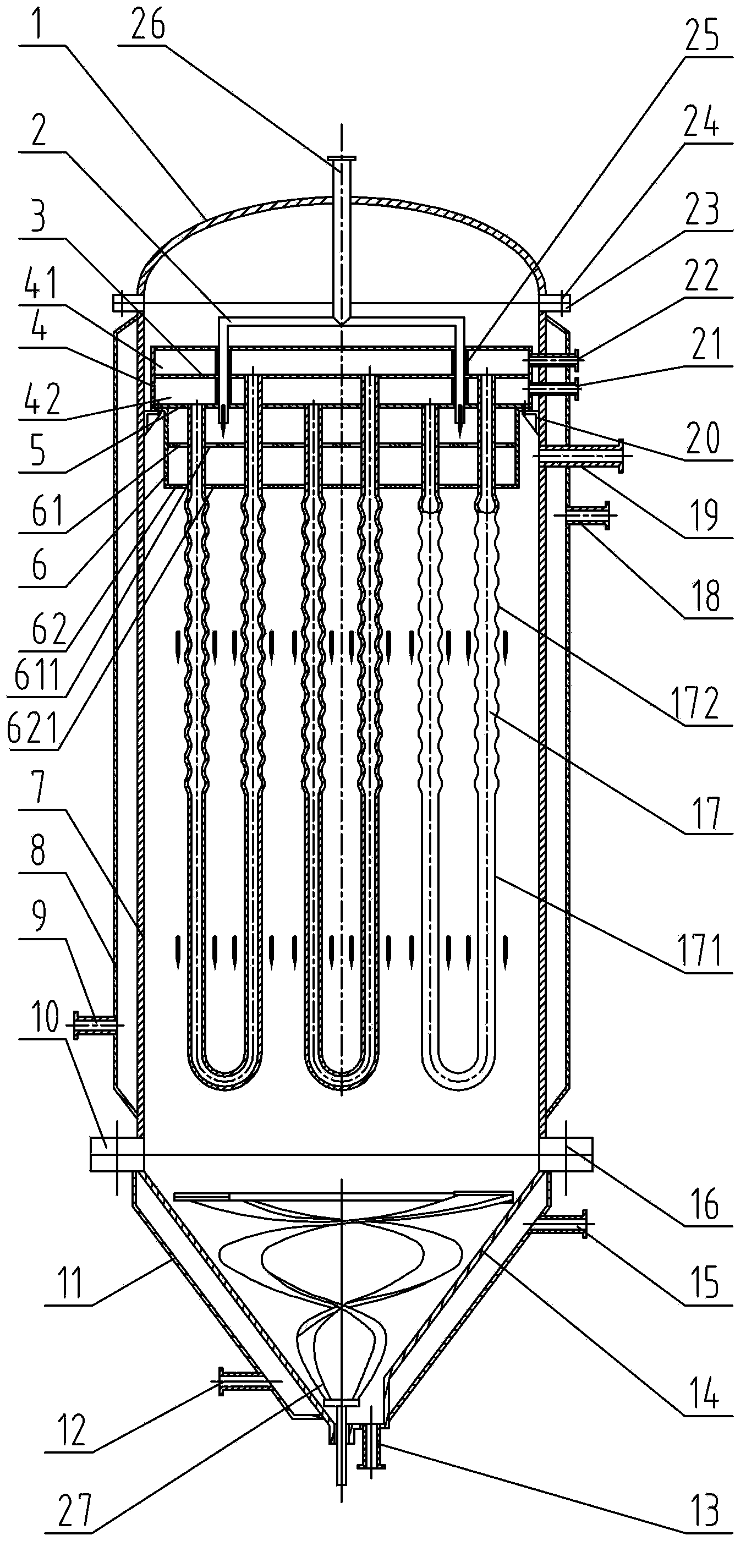
[0060] Embodiment 3, with reference to attached image 3 , 4 , 5a, 5b, 5c, 5d.

[0061] In this embodiment, the upper section of the straight part of the U-shaped falling film tube 17 is a corrugated tube or bellows 172, and the lower section is a round tube 171. The upper section and the lower section are coaxial, and the length of the upper section is determined according to the viscosity of the feed melt. If the viscosity is high, the length will be short, otherwise it will be long. The length of the lower section is determined according to the viscosity of the discharged melt. If the viscosity is high, the length will be long, otherwise it will be short; The crest diameter D of the U-shaped falling film tube 17 2 5-100mm, height 0.5-30m.

[0062] Other parts and implementation method of this embodiment are the same as embodiment 1, in image 3 , the reference numerals and figure 1 The same means the same meaning.

[0063] In this embodiment, according to the viscosit...


PUM

PropertyMeasurementUnit
heightaaaaaaaaaa

Abstract

The invention discloses a melt polycondensation reaction method which comprises steps as follows: a molten monomer blend or prepolymer slides down along the outer wall of a U tube to carry out polycondensation reaction, wherein a heat-transfer medium circularly flows in the U tube; molten masses in all U tubes are mixed at the lower part of a polycondensation reactor to be subjected to stirring reaction and mixing homogeneization; and the product is discharged after the reaction finishes. A polycondensation reactor for implementing the method comprises a vertical shell, an upper end socket, a lower end bottom shell, U tubes, a heat-transfer system, a film distributor, a helical ribbon stirrer and the like. The reactor has the advantages of simple structure, sufficient heat exchange, large film formation area, uniform reaction temperature, high polycondensation efficiency and the like, satisfies the plug flow in the process, and can be used for melt polycondensation reaction for producing polyethylene terephthalate, polytrimethylene terephthalate, polybutylene terephthalate, polyethylene naphthalate, polyamide, polycarbonate and the like.

Description

technical field [0001] The invention relates to a melting polycondensation reaction method, melting polycondensation reaction equipment and a falling film element outside a tube. Background technique [0002] The implementation methods of polycondensation reaction include melt polycondensation, solution polycondensation, solid-state polycondensation and interfacial polycondensation, etc. Among them, melt polycondensation has obvious advantages in terms of product quality, economy, environmental protection and industrial implementation. Therefore, most polyesters Polyethylene terephthalate (PET), polytrimethylene terephthalate (PTT), polybutylene terephthalate (PBT), poly Ethylene naphthalate (PEN), polyamide, polycarbonate, etc. The key to the implementation of the melt polycondensation process lies in the reactor. An ideal polycondensation reactor requires good material flow and mixing state, high heat and mass transfer efficiency, and the process satisfies plug flow, so a...

Claims


Application Information

Patent Timeline
Patent Type & Authority Patents(China)
IPC IPC(8): C08G63/78B01J19/24B01J19/32
CPCC08G63/785C08G64/205C08G69/04B01J10/02B01J19/247B01J19/1887B01J2219/00078
Inventor 陈文兴
Owner ZHEJIANG SCI-TECH UNIV
Learn More