A pressure bearing assembly and method of use

A pressure-bearing plate and component technology, applied in the field of pressure-bearing plate components, can solve the problems of small pull-out force, weak pull-out force, small application range, etc., to achieve improved pull-out force, ingenious structure, and improved application range Effect

Active Publication Date: 2016-06-01
郭财宝
View PDF6 Cites 0 Cited by
  • Summary
  • Abstract
  • Description
  • Claims
  • Application Information

AI Technical Summary

Problems solved by technology

[0002] Soil nail support and bolt support are widely used in foundation pit enclosure engineering and slope stabilization engineering. The cost of soil nail support is low and the construction is convenient, but the length and diameter of the soil nail are small, and the average pullout force is small. , is only applicable to general strata, so the scope of application is small, and often cannot meet the design requirements, and this kind of soil nails cannot be prestressed well, and the pull-out resistance is not strong, so they cannot play a good role; The length, diameter and pullout resistance are greater than those of soil nails, but their cost is relatively high. The construction needs to go through two processes of drilling first, then inserting metal materials, and then grouting, which cannot be completed at one time, which increases the cost; Filling soil, soft soil, silt, silt, and sand and pebbles are easy to collapse holes, making it difficult to form holes. Generally, full-sleeve hole forming is used to form holes. It is easy to collapse the hole in the center, so the construction difficulty is high. Because the diameter of the steel bar or anchor bar used as the anchor is generally small, the anchoring body's holding force on the steel bar and the anchor bar is too small, and the friction between the anchor body and the soil cannot be fully exerted. , which requires a longer anchor pile length to meet the anchor pull force requirements, increasing the construction cost

Method used


Image

  • A pressure bearing assembly and method of use
  • A pressure bearing assembly and method of use
  • A pressure bearing assembly and method of use

Examples


Embodiment

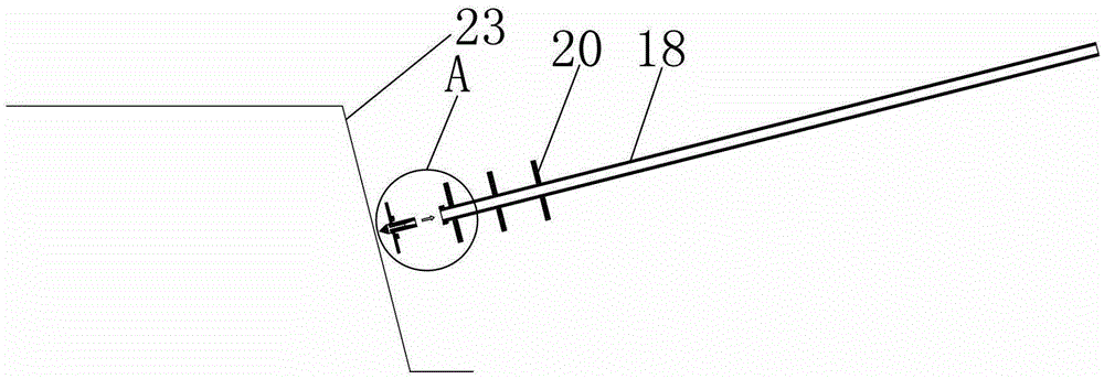
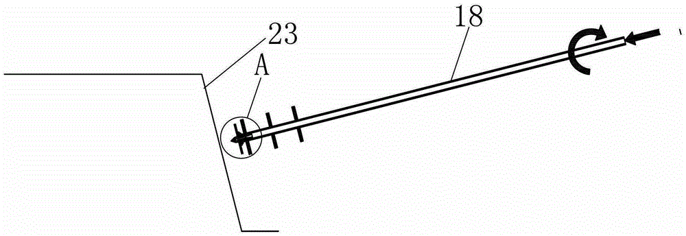
[0037] Embodiment: a kind of bearing plate type anchor pile, as Figure 8 , Figure 9 As shown, it includes a pressure bearing plate assembly 1 and steel bars 14. The pressure bearing plate assembly 1 is located deep in the formation 23. The steel bars 14 are inserted in the formation 23 and connected with the pressure bearing plate assembly 1. The formation 23 is all the layers except the bedrock. The formation, the bearing plate assembly 1 , the steel bar 14 and the cement soil 21 wrapped around the steel bar and filled with cement slurry or cement powder and stirred by the drill pipe blades are combined to form the anchor pile 22 .

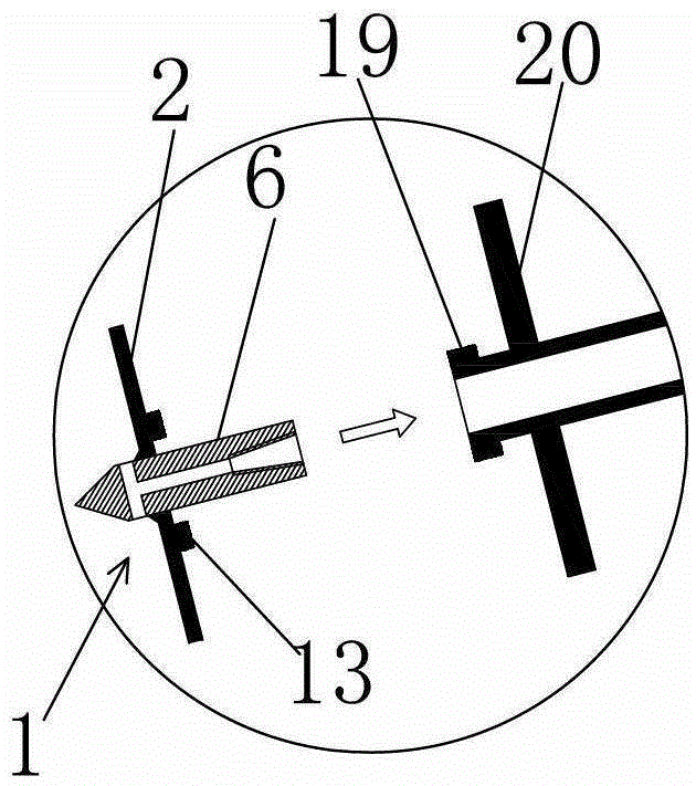
[0038] Described reinforcing bar 14 adopts reinforcing bar, as Figure 10-16As shown, the pressure bearing plate assembly 1 includes a pressure bearing plate 2, the pressure bearing plate 2 can be circular, square or other shapes, and a joint 3 is pierced at the center of the pressure bearing plate 2, and the joint 3 and the pressure bearing p...


PUM


Abstract

The invention discloses a pressure bearing plate assembly and a utilization method. The pressure bearing plate assembly comprises a pressure bearing plate; a connector which is arranged in the center of the pressure bearing plate in a penetrating mode is fixedly connected with the pressure bearing plate; two ends of the connector expose outside the pressure bearing plate; the end surface of the rear end of the connector is provided with a screw hole along a connector axial direction. The pressure bearing plate is mainly used in combination with a drill rod and a reinforcing bar anchor rod in construction and pulling resistance force of the reinforcing bar anchor rod can be improved due to the fact that the superficial area of the pressure bearing plate assembly is large; cooperation of the connector and the drill rod can play a role as a plug; the connector can be in threaded connection with the reinforcing bar anchor rod through the screw hole; a soil cutter which is arranged on the pressure bearing plate plays a role in stirring soil, so that the whole pressure bearing plate assembly is artistic in structure and is multifunctional. The pressure bearing plate assembly is applied to stratums except base rocks.

Description

technical field [0001] The invention relates to the technical field of soil excavation, slope stability and underground structure anti-floating and anti-lifting, and in particular to a pressure-bearing plate assembly used for foundation pit enclosure, side slope reinforcement, and underground structure anti-lifting and anti-floating and its use method . Background technique [0002] Soil nail support and bolt support are widely used in foundation pit enclosure engineering and slope stabilization engineering. The cost of soil nail support is low and the construction is convenient, but the length and diameter of the soil nail are small, and the average pullout force is small. , is only applicable to general strata, so the scope of application is small, and often cannot meet the design requirements, and this kind of soil nails cannot be prestressed well, and the pull-out resistance is not strong, so they cannot play a good role; The length, diameter and pullout resistance are ...

Claims


Application Information

Patent Timeline
Patent Type & Authority Patents(China)
IPC IPC(8): E02D5/74E02D5/54
Inventor 郭财宝
Owner 郭财宝
Why Eureka
Try Eureka