
Flow-drying exhaust gas treatment device and method

A technology of tail gas treatment and airflow drying, which is applied in the direction of drying gas arrangement, separation method, drying solid materials, etc., can solve the problems of waste, environmental heat pollution, environmental pollution, etc., and achieve the effect of stable quality, stable pressure and reduced energy consumption

Inactive Publication Date: 2013-09-25
ZHEJIANG SHENGHUA BIOK BIOLOGY
View PDF11 Cites 5 Cited by
  • Summary
  • Abstract
  • Description
  • Claims
  • Application Information

AI Technical Summary

Problems solved by technology

[0002] The dry exhaust gas discharged through the airflow drying equipment has a high temperature, which will cause thermal pollution to the environment, and at the same time cause thermal pollution and energy waste; and the exhaust gas contains odor molecules of various components. If it is directly discharged, the odor molecules will pollute Environment: the air flow drying equipment requires a large amount of air, especially the harmful odor molecules of the dry materials can not be treated for the pollution of the environment, basically it is simply treated and discharged by water spraying, and the odor molecules are complex, mostly organic matter that is difficult to dissolve in water , the processing effect is basically ineffective

Method used


Image

  • Flow-drying exhaust gas treatment device and method
  • Flow-drying exhaust gas treatment device and method

Examples


Embodiment Construction

[0021] The present invention will be further described below in conjunction with accompanying drawing:

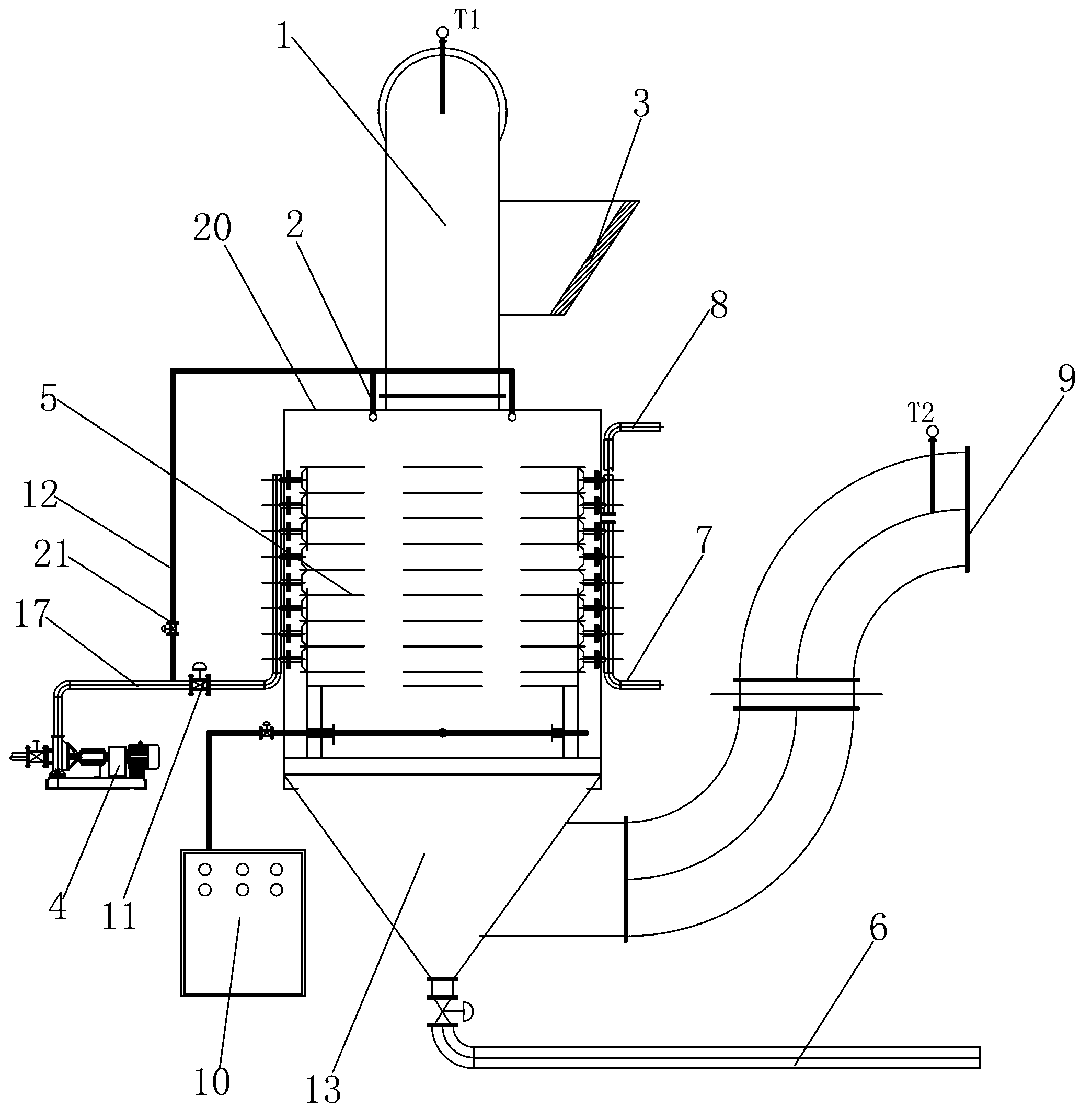
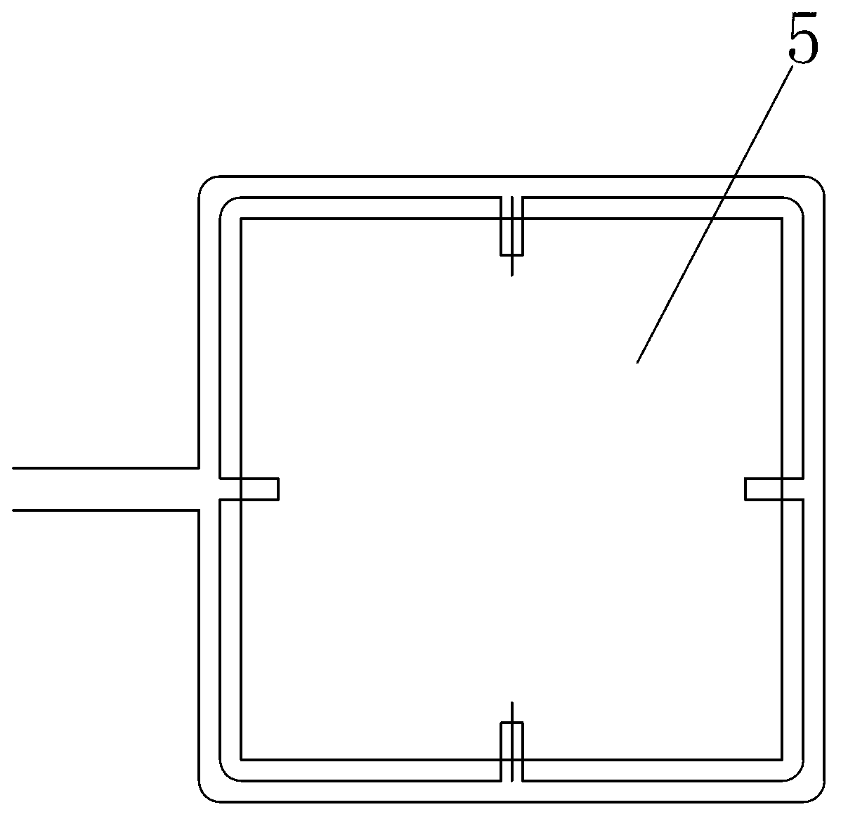
[0022] Such as figure 1 , 2 , an airflow drying tail gas treatment device, including a housing 20, a heat exchanger 5 is arranged in the housing 20, an exhaust gas inlet pipe 1 is connected to the upper end of the housing 20, an air supplement inlet 3 is arranged on the tail gas inlet pipe 1, and the housing The lower end of 20 is connected to the low-temperature air outlet 9, and the heat exchanger 5 is provided with a cleaning system, and the bottom of the heat exchanger 5 is also provided with an ozone generator 10. The cleaning system includes a cleaning nozzle 2 arranged on the top of the housing 20 , the cleaning nozzle 2 is connected to the circulating water pump 4 through the water spray pipe 12 , and a water collector 13 is arranged at the bottom of the housing, and the water collector is connected to the water outlet pipe 6 . The heat exchanger 5 is provided wit...


PUM


Abstract

The invention discloses a flow-drying exhaust gas treatment device and method. Exhaust gas enters a heat exchanger from an exhaust gas inlet pipe. The heat exchanger guides circulating water to cool through a circulating pump and a circulating water inlet pipe. Water on the upper portion of the heat exchanger is discharged through a hot water outlet pipe, and water on the lower potion of the heat exchanger flows to a circulating water tank through a circulating water return pipe. Condensate water generated by cooling the exhaust gas is discharged through a water collector at the bottom of the heat exchanger and a water outlet of a water outlet pipe. Flow of the circulating water is controlled to adjust the air temperature of the output of the heat exchanger to be lower than the temperature required by art. Heat-exchanged low-temperature air is transmitted to drying equipment through a lower-temperature air outlet. When the temperature of the exhaust gas inlet is lower than 35 DEG C, an ozone generator is turned on to guide ozone into a system; when the odor concentration at the lower-temperature air outlet is lower than 200 equivalents, the ozone generator is turned off, and a washing system is turned on to wash the heat exchanger. Harmful substances in the exhaust gas can be removed basically, and the discharged low-temperature gas can be used circularly.

Description

technical field [0001] The invention relates to a method and a device for airflow drying tail gas treatment, in particular to a method and a device for recycling and utilizing odor molecules and waste heat in the environmentally friendly oxidation decomposition tail gas. Background technique [0002] The dry exhaust gas discharged through the airflow drying equipment has a high temperature, which will cause thermal pollution to the environment, and at the same time cause thermal pollution and energy waste; and the exhaust gas contains odor molecules of various components. If it is directly discharged, the odor molecules will pollute Environment: the air flow drying equipment requires a large amount of air, especially the harmful odor molecules of the dry materials can not be treated for the pollution of the environment, basically it is simply treated and discharged by water spraying, and the odor molecules are complex, mostly organic matter that is difficult to dissolve in wa...

Claims


Application Information

Patent Timeline
Patent Type & Authority Applications(China)
IPC IPC(8): F26B21/04F26B25/00B01D53/76B01D53/44
Inventor 洪景学齐铁峰李俊国
Owner ZHEJIANG SHENGHUA BIOK BIOLOGY
Learn More