Method for measuring antenna deformation of ship-borne radio measuring equipment

A technology of radio equipment and radio measurement, which is applied in the direction of measurement device, measurement angle, mapping and navigation, etc., and can solve the problems such as the inability to realize deformation measurement of shipborne radio measurement equipment.

Inactive Publication Date: 2013-09-25
CHANGCHUN INST OF OPTICS FINE MECHANICS & PHYSICS CHINESE ACAD OF SCI
View PDF7 Cites 11 Cited by
  • Summary
  • Abstract
  • Description
  • Claims
  • Application Information

AI Technical Summary

Problems solved by technology

[0004] In order to solve the problem that the existing technology cannot realize the deformation measurement of the ship-borne radio measure...

Method used


Image

  • Method for measuring antenna deformation of ship-borne radio measuring equipment
  • Method for measuring antenna deformation of ship-borne radio measuring equipment
  • Method for measuring antenna deformation of ship-borne radio measuring equipment

Examples


specific Embodiment approach 1

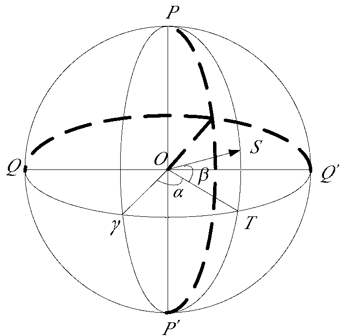
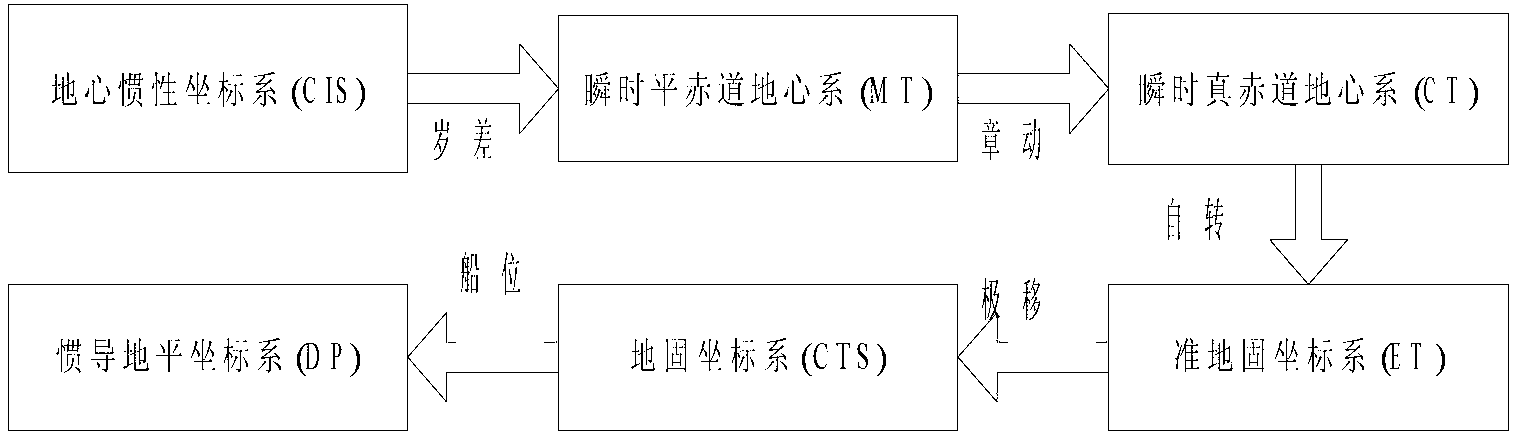
[0026] Specific implementation mode 1. Combination figure 1 and figure 2 To illustrate this embodiment, the coordinate systems involved in this embodiment include CIS—earth-centered inertial coordinate system (J2000.0 coordinate system), MT—instantaneous flat equatorial earth-centered system, CT—instantaneous true equatorial earth-centered system, ET—quasi Earth-fixed coordinate system, CTS—ground-fixed coordinate system, DP—inertial navigation horizon system, b—deck coordinate system, s—star sensor coordinate system.

[0027] Basic Euler angle rotation transformation matrix R x (θ),R y (θ),R z (θ) represent the matrices formed by rotating θ counterclockwise around the X, Y, and Z axes, respectively, and have the following standard form:

[0028] R x ( θ ) = 1 0 0 ...


PUM


Abstract

The invention discloses a method for measuring antenna deformation of ship-borne radio measuring equipment, and relates to the field of spacecraft attitude control ground application. The method solves the problem that in the prior art, self-deformation of the ship-borne radio measuring equipment cannot be measured. The method comprises the steps that 1 a star sensor SS1 and a star sensor SS2 are installed at the position of a base of the ship-borne radio equipment and at the position of the center of the three axes respectively, 2 when a ship docks and displaces, radio antenna directing angles satisfy the equations that A=0 degree and E=90 degrees and are locked, and installation matrixes of the two star sensors are marked, 3 when the ship sails, the antenna directing angles which satisfy the equations that A=0 degree and E=90 degrees are locked, the two star sensors conduct star measuring simultaneously and ship body attitude angles at the position of the base and at the position of the center of the three axes are resolved respectively, and 4 an antenna deformation matrix is resolved and an antenna equivalent deformation angle is solved. According to the method for measuring antenna deformation of the ship-borne radio measuring equipment, astronomical refraction correction is conducted on star sensor attitude angles under the inertial navigation horizontal system, and the calculating precision of the deformation angle is improved.

Description

technical field [0001] The invention relates to the ground application field of spacecraft attitude control, in particular to a method for measuring antenna deformation of radio measuring equipment. According to the principle of the attitude determination algorithm of the star sensor, the deformation angle of the three-axis center of the radio equipment antenna relative to the antenna base is accurately calibrated. Background technique [0002] The star sensor is a high-precision attitude sensor that uses stars as a reference. It can be settled by detecting stars in different positions on the celestial sphere. It has the ability of autonomous navigation and plays an important role in the control system and attitude measurement process of various aircraft. effect. The star sensor has the characteristics of good concealment, wide application range, high reliability, high precision, and can work independently around the clock. [0003] my country's aerospace survey ship adopt...

Claims


Application Information

Patent Timeline
IPC IPC(8): G01B21/32G01C1/00
Inventor 郭敬明何昕魏仲慧张同双张磊王子辰
Owner CHANGCHUN INST OF OPTICS FINE MECHANICS & PHYSICS CHINESE ACAD OF SCI
Why Eureka
Try Eureka