Double-shaft tracking support

A dual-axis tracking and bracket technology, applied in the support structure of photovoltaic modules, photovoltaic modules, mobile/directional solar collectors, etc., can solve the problems that hinder the commercial development of tracking technology, increase road and foundation requirements, and difficult installation and maintenance. increase and other problems, to achieve the effect of high market promotion value, low production cost, and elimination of huge eccentricity

Active Publication Date: 2013-09-25
刘建中
View PDF6 Cites 18 Cited by
  • Summary
  • Abstract
  • Description
  • Claims
  • Application Information

AI Technical Summary

Problems solved by technology

However, most of the existing solar dual-axis tracking technologies have high costs due to complex structures and other reasons. In the cost composition of photovoltaic power generation systems, they even exceed 40% of the total investment of power stations; compared to 30%-50% of power generation Improvement, tracking has lost commercial value
Moreover, the tracking itself consumes power. Due to the large shadow area, the tracking occupies more land than the fixed installation. The maintenance and repair of the equipment requires additional technical personnel, and the risk of device operation is greater than that of the fixed installation. At the same time, in order to To reduce the cost of tracking, the manufacturers of the tracking brackets are currently making the biaxial tracking devices larger and larger, which has caused a series of problems such as increased wind resistance, increased difficulty in installation and maintenance, and increased requirements for roads and foundations. The effect produced by dual-axis tracking technology is much less attractive, which seriously hinders the commercial development of tracking technology

Method used


Image

  • Double-shaft tracking support
  • Double-shaft tracking support
  • Double-shaft tracking support

Examples


Embodiment 1

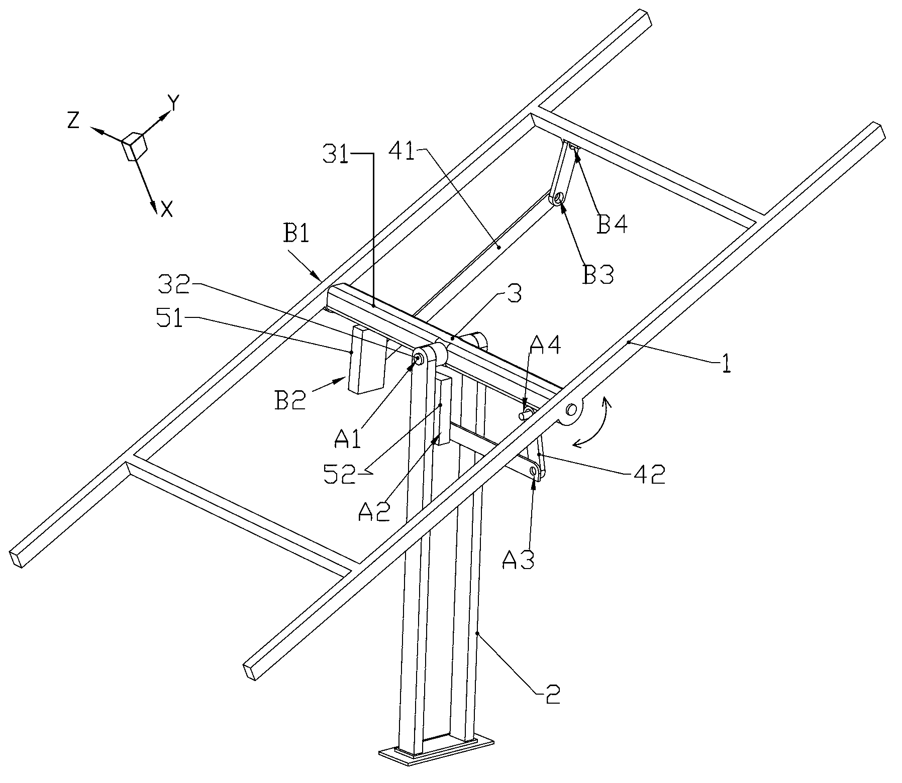
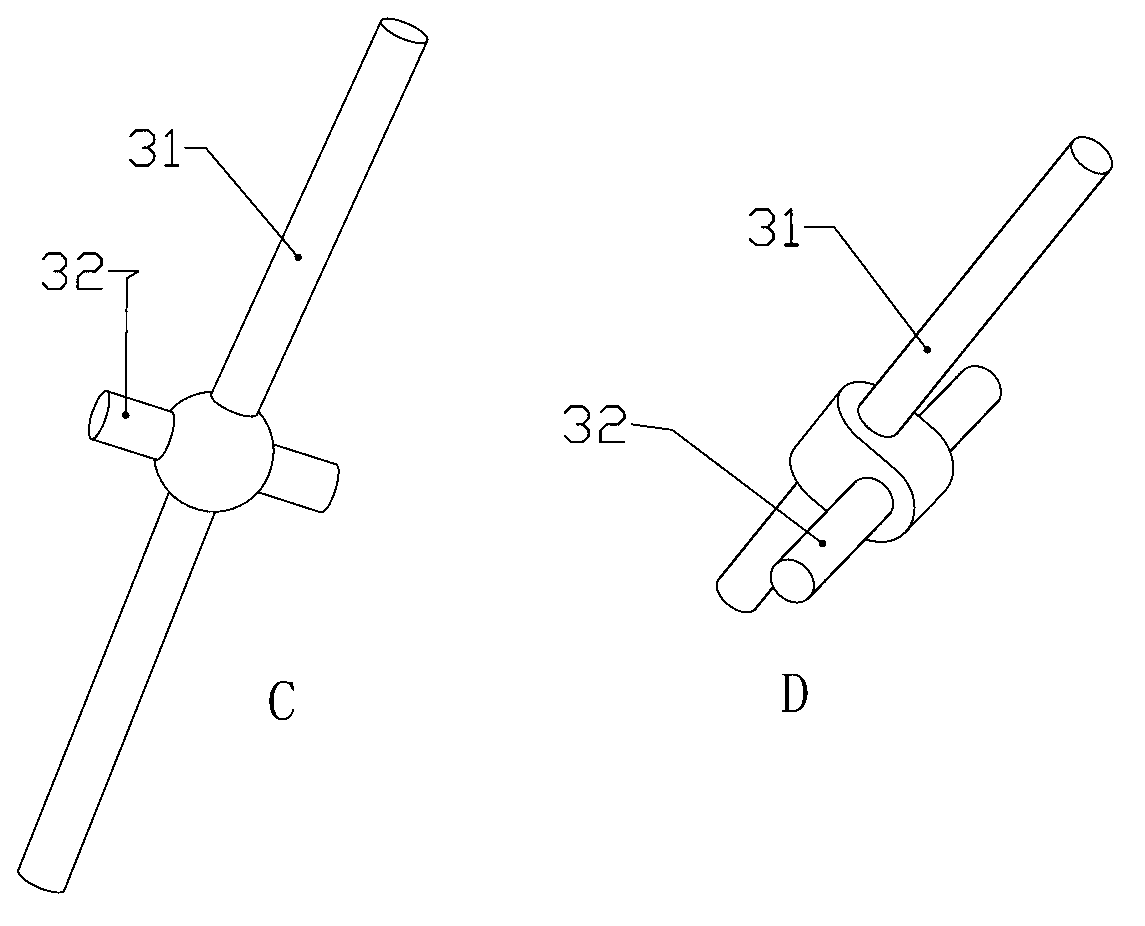
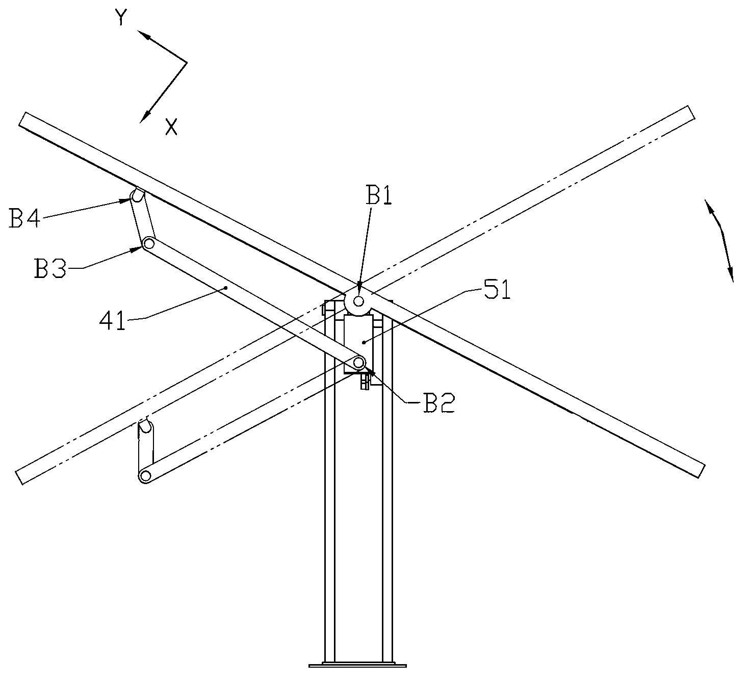
[0040] like Figure 1~3As shown, the dual-axis tracking bracket includes a bracket 1, a column 2, a central pivot shaft 3, a rotation angle adjustment device and an elevation angle adjustment device. For ease of description, first define the direction parallel to the plane where bracket 1 is located and along the solar daily orbit as the Y direction (rotation angle), and define the direction parallel to the plane where bracket 1 is located and along the solar annual orbit as the Z direction ( elevation angle), then the direction perpendicular to the YZ plane and facing the back of the bracket 1 is the X direction.

[0041] see figure 1 , in one embodiment, the bracket 1 may be a steel pipe welded or bolted frame structure for fixing solar modules. Obviously, the above-mentioned frame structure is not limited thereto, but can be made of any other suitable materials, such as aluminum alloy profiles and the like. like figure 1 As shown, in one embodiment, the upright column 2...

Embodiment 2

[0055] like Figure 4 As shown, the difference from Embodiment 1 is that the first transmission part of the angle adjustment device of the tracking bracket is composed of a first moment arm lever 71 and a first transmission rope 711 and a second transmission rope 712 of equal length. One end of a transmission rope 711 is connected on the bracket 1, and the other end is connected with the end of the first moment arm lever 71; the middle of the first moment arm lever 71 is fixedly connected with the output shaft of the first driving part 51, and the second transmission One end of the rope 712 is connected on the bracket 1, and the other end is connected with the other end of the first moment arm bar 71, and tensioned; as Figure 4 As shown, the first moment lever 71, the bracket 1, the first transmission rope 711 and the second transmission rope 712 jointly form a parallelogram linkage mechanism, and the linkage mechanism is driven by the first driving part 51. Get some exercis...

Embodiment 3

[0059] like Figure 5 As shown, the difference from Embodiment 1 or 2 is that the second transmission part of the elevation angle adjustment device of the tracking bracket is an elevation angle adjustment rod 61, one end of which is fixedly connected to the corner pivot shaft 31 of the central pivot shaft 3 , the other end is fixedly connected to the body of the first driving part 51, on the elevation angle adjustment rod 61, an array of positioning holes 62 is set according to the change law of the sun's annual operating altitude angle, and on the column 2, two belts are fixed up and down in layers The positioning plate with the positioning hole forms the positioning structure 64, the elevation angle adjustment rod 61 passes through it, and a T-shaped positioning pin 63 passes through the hole of the positioning structure 64 and the elevation angle adjustment rod 61 from top to bottom, and adjusts the elevation angle. The rod 61 is locked to achieve the purpose of locking the...


PUM


Abstract

The invention discloses a double-shaft tracking support. The double-shaft tracking support comprises a bracket, a stand column, a center pivotal shaft, a turn angle adjusting device and an elevation angle adjusting device which are all used for bearing a solar component. The bracket is connected with the stand column through the center pivotal shaft, a turn angle pivotal shaft of the center pivotal shaft is hinged to the bracket so that the bracket can rotate in the turn angle direction, and an elevation angle pivotal shaft of the center pivotal shaft is hinged to the stand column so that the bracket can rotate in the elevation angle direction. The turn angle adjusting device comprises a first transmission part and a first driving part, wherein the first transmission part is connected to the bracket, and the first driving part is mounted on the turn angle pivotal shaft and is matched with the first transmission part. The elevation angle adjusting device comprises a second transmission part and a second driving part, wherein the second transmission part is connected to the elevation angle pivotal shaft or the bracket, and the second driving part is mounted on the stand column and is matched with the second transmission part. The double-shaft tracking support has the advantages of being firm in structure, low in cost, low in power consumption, stable in operation, convenient to install, transport and maintain daily and the like.

Description

technical field [0001] The invention relates to the technical field of solar energy utilization equipment, in particular to a support device capable of biaxially tracking sunlight. Background technique [0002] In a photovoltaic power generation system, the brackets used to support solar cell modules are generally divided into fixed brackets and tracking brackets. Among them, tracking brackets are further divided into horizontal single-axis tracking brackets, oblique single-axis tracking brackets and dual-axis tracking brackets. According to research, after adopting biaxial tracking technology, solar cell modules made of ordinary crystalline silicon materials can generate more than 30%-50% more power than fixedly installed solar cell modules due to different lighting conditions in different regions. However, most of the existing solar dual-axis tracking technologies have high costs due to complex structures and other reasons. In the cost composition of photovoltaic power gen...

Claims


Application Information

Patent Timeline
Patent Type & Authority Applications(China)
IPC IPC(8): G05D3/00F24S50/20
CPCF24S30/455F24S2030/131H02S20/32Y02E10/47Y02E10/50
Inventor 刘建中
Owner 刘建中
Why Eureka
Try Eureka