Reality testing method for design drawing

A verification method and design drawing technology, applied in calculation, special data processing applications, instruments, etc., can solve problems such as low efficiency, large error, slow speed, etc., and achieve the effect of reducing error and reducing quick reference

Active Publication Date: 2013-09-25
丁成波
3 Cites 7 Cited by

AI-Extracted Technical Summary

Problems solved by technology

The error of the first method is too large and may even be unrecognizable due to the similarity of topography; the second method is slow and inefficient; the third method is the most accurate method as a surveying profession, but the slowest and costly Most time consuming and usuall...

Method used

In above-mentioned several embodiments, described Oruxmaps software is installed on the panel computer with navigation function, mobile phone or ultrabook. Using the navigation function of the Oruxmaps software, the user can record the user's movement track through the navigation function, and the user can specifically check whether its position corresponds to the position in the design map when...

Abstract

The invention relates to the field of computer image processing and particularly relates to a reality testing method for a design drawing. The reality testing method comprises the following steps of: carrying out reality longitude-latitude coordinate mapping on the design drawing to enable a picture coordinate of each pixel point on the design drawing to be corresponded to a reality longitude-latitude coordinate, and enabling the design drawing subjected to the coordinate mapping to be corresponded to the real earth; or covering the design drawing subjected to the coordinate mapping on a map of the real earth, wherein the longitude-latitude coordinate of the design drawing is corresponding to that of the real earth. According to the reality testing method for the design drawing, the corresponding between the design drawing and the real earth is realized, so that the design drawing can be viewed based on the map of the real earth and subjected to reality testing, and users can conveniently carry out various relevant outdoor earth applications to reduce errors and fast consulting offset according to the design drawing.

Application Domain

Special data processing applications

Technology Topic

Image processingLongitude +6

Image

  • Reality testing method for design drawing
  • Reality testing method for design drawing

Examples

  • Experimental program(1)

Example Embodiment

[0009] In order to make the purposes, technical solutions and advantages of the embodiments of the present invention clearer, the technical solutions in the embodiments of the present invention will be clearly and completely described below with reference to the accompanying drawings in the embodiments of the present invention. Obviously, the described embodiments These are some embodiments of the present invention, but not all embodiments. Based on the embodiments of the present invention, all other embodiments obtained by those of ordinary skill in the art without creative efforts shall fall within the protection scope of the present invention.
[0010] The present invention will be further described in detail below through specific embodiments and in conjunction with the accompanying drawings.
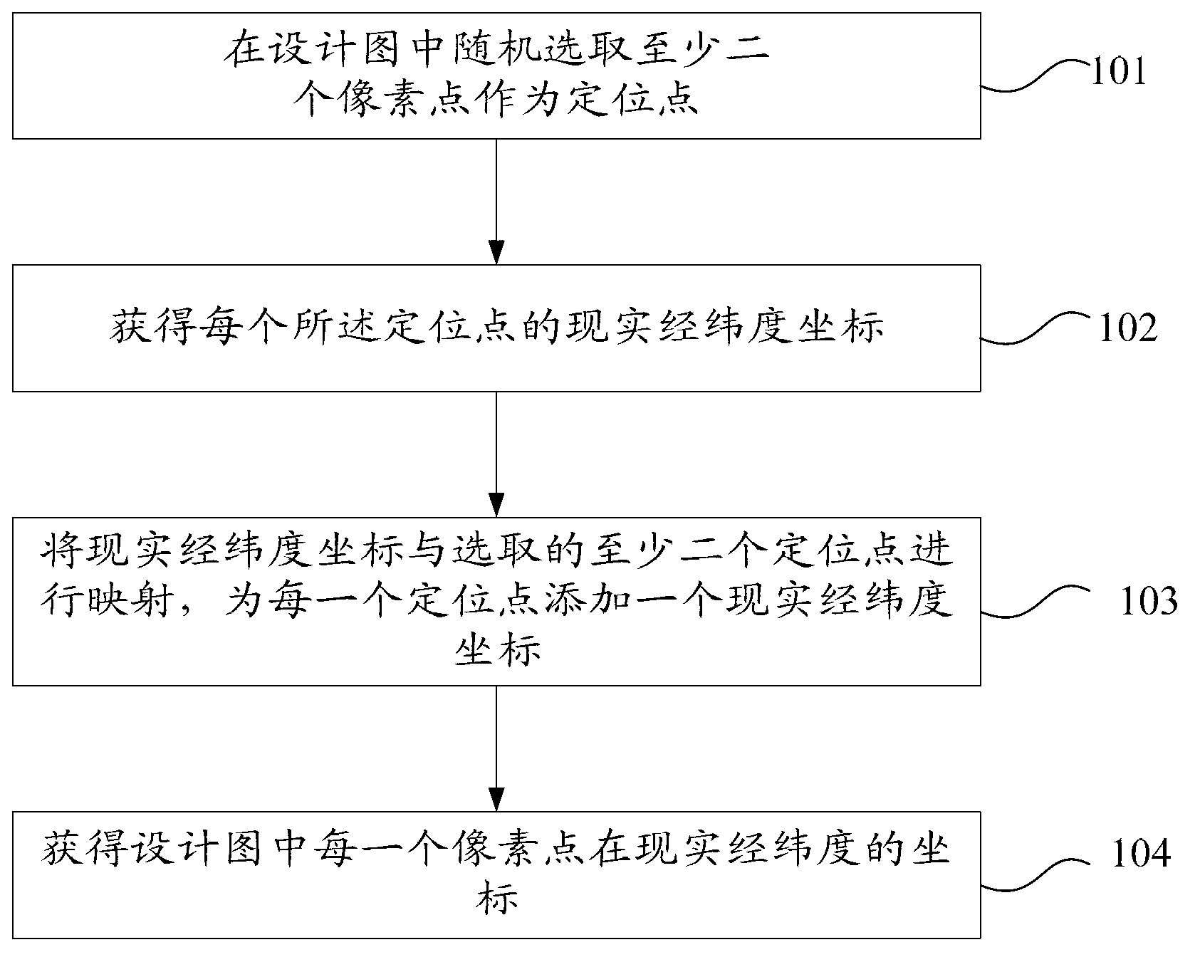
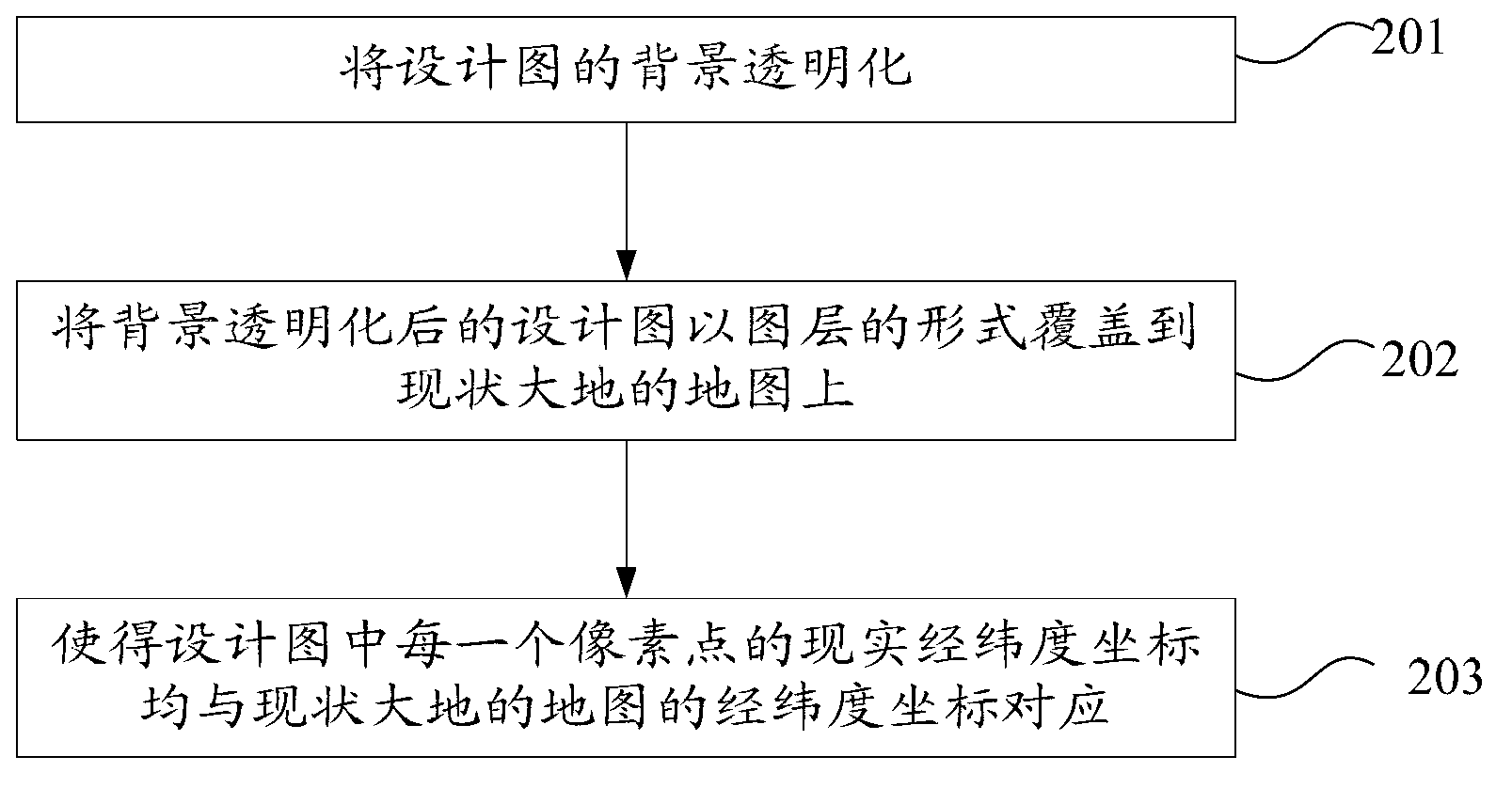
[0011] The reality verification method of the design drawing provided by the embodiment of the present invention includes:
[0012] Perform real latitude and longitude coordinate mapping on the design drawing, so that the picture coordinates of each pixel on the design drawing correspond to a real longitude and latitude coordinate; and map the design drawing after the real longitude and latitude coordinate mapping with the current situation; or map the actual longitude and latitude coordinates. The mapped design drawing is overlaid on the map of the existing earth in the form of a layer, and the latitude and longitude coordinates of the design drawing correspond to the longitude and latitude coordinates of the map of the existing earth.
[0013] The reality verification method of the design drawing in the above-mentioned embodiment of the present invention is to map the design drawing to the coordinates of the actual longitude and latitude, so that the picture coordinates of each pixel on the design drawing correspond to a real longitude and latitude coordinates, and the actual longitude and latitude coordinates are mapped after the actual longitude and latitude coordinates are mapped. The design drawing corresponding to the existing earth; or overlay the design drawing after mapping the actual latitude and longitude coordinates on the map of the existing earth in the form of a layer, and the latitude and longitude coordinates of the design drawing correspond to the latitude and longitude coordinates of the map of the existing earth. In this way, the correspondence between the design drawing and the existing earth is realized, so that the design drawing can be viewed on the basis of the map of the existing earth, and the design drawing can be verified realistically, which is convenient for the user to carry out various outdoor earth applications according to the design drawing to reduce errors. and Quick Reference Bias.
[0014] figure 1 It is a schematic flowchart of a method for verifying the reality of a design diagram provided by another embodiment of the present invention. On the basis of the above embodiment, the mapping of the actual latitude and longitude coordinates to the design drawing includes:
[0015] Step 101: randomly select at least two pixels as positioning points in the design drawing;
[0016] Step 102: Obtain the actual latitude and longitude coordinates of each of the positioning points;
[0017] Step 103: Map the real latitude and longitude coordinates with the selected at least two positioning points, and add a real latitude and longitude coordinate for each positioning point;
[0018] Step 104: Obtain the coordinates of each pixel in the design drawing in the real latitude and longitude.
[0019] In the second embodiment, at least three pixel points are randomly selected as positioning points in the design drawing. Obtain the actual latitude and longitude coordinates of each said anchor point in the design drawing. For example, in the design drawing of a road planning, a certain point in a certain road is planned, and its actual longitude and latitude coordinates should be XX°XX'XXX" east longitude and YY°YY'YYY" north latitude. Select this point in the design drawing. The pixel point corresponding to the point, and the real latitude and longitude coordinates of the pixel point are mapped with the image coordinates of the pixel point. When the design drawing is drawn, the computer will automatically add a picture coordinate for each pixel of the design drawing. Select at least two pixel points as positioning points in the design drawing, and calculate the actual longitude and latitude coordinates of each pixel point through the scale of the design drawing, the actual latitude and longitude coordinates of the two positioning points, and the image coordinates of the two positioning points. .
[0020] In this embodiment, the randomly selecting at least two pixel points in the design drawing as positioning points includes: randomly selecting 4-9 pixel points as positioning points in the design drawing. The more positioning points you select, the higher the accuracy of mapping the design drawing to the latitude and longitude coordinates. However, selecting too many positioning points will waste time and computer system resources, so 4-9 are randomly selected in the design drawing. Pixels are used as anchor points.
[0021] figure 2 It is a schematic flowchart of a method for verifying the reality of a design diagram provided by another embodiment of the present invention. On the basis of the above two embodiments, in the reality verification method of the design drawing, the design drawing after the real latitude and longitude coordinate mapping is covered on the map of the current earth in the form of a layer, and the longitude and latitude coordinates of the design drawing are the same as The latitude and longitude coordinates of the current map of the earth correspond to:
[0022] Step 201: Make the background of the design drawing transparent;
[0023] Step 202: overlay the design drawing with the transparent background on the map of the current land in the form of a layer;
[0024] Step 203: Make the actual latitude and longitude coordinates of each pixel in the design map correspond to the latitude and longitude coordinates of the map of the current land.
[0025] In the third embodiment, the background of the design drawing is first made transparent, and then the design drawing after the transparent background is overlaid on the map of the current earth in the form of layers, so that the design drawing represents buildings, roads, etc. The lines will stand out, and you can see the current map of the earth through the background of the design drawing. The actual longitude and latitude coordinates of each pixel in the obtained design drawing are positioned with the longitude and latitude coordinates of the displayed map. For example, in a certain design drawing , the longitude and latitude of a certain pixel point is: east longitude XX°XX'XXX", north latitude YY°YY'YYY", then when the design drawing is covered on the map of the current earth, the pixel point and the longitude and latitude are also east longitude XX°XX 'XXX' corresponds to the point of north latitude YY°YY'YYY', so that the design drawing can be completely covered on the map of the current earth, and the user can compare the design drawing and the map of the current earth to make the design drawing reality. verify.
[0026] In the above three embodiments, OziExplorer software is used to randomly select at least two pixel points in the design drawing as positioning points; obtain the actual latitude and longitude coordinates of each positioning point in the design drawing; The picture coordinates in the design drawing are mapped with the actual longitude and latitude coordinates of the positioning point in the planning, and a real longitude and latitude coordinates are added to each positioning point; the actual longitude and latitude coordinates of each pixel in the design drawing are obtained.
[0027] OziExplorer is a software that can locate the map. When using the OziExplorer software to realize the above functions, you need to import the design drawing into the OziExplorer software to open, and the OziExplorer software will automatically display the picture coordinates of the design drawing for the user. The user can use the mouse to randomly select a pixel point in the open design drawing as the positioning point, and the actual longitude and latitude coordinates of the pixel point on the design drawing can be obtained through actual measurement, or can be obtained in advance when designing in the design drawing. Therefore, the actual latitude and longitude coordinates of the pixel point are added to the pixel point. The user can select multiple pixel points as positioning points. Generally, more than 3 points are selected. Preferably, the number of selected positioning points is 4-9, which can more accurately compare the image coordinates of the entire design drawing with the actual latitude and longitude coordinates. to map.
[0028] In the above and the above embodiments, PHOTOSHOP or AUTOCAD software can be used to make the background of the design drawing transparent; the design drawing after the background transparentization is overlaid on the map of the current earth in the form of layers; The real latitude and longitude coordinates of the pixel point correspond to the latitude and longitude coordinates of the current map of the earth.
[0029] Oruxmaps software is an outdoor navigation software. You can use the Oruxmaps software to open the user-made map, and open the design drawing after the latitude and longitude coordinate mapping. Use PHOTOSHOP or AUTOCAD software to make the background of the design transparent, leaving only the colored lines in the design, and use the Oruxmaps software to overlay the transparent background design on the map of the current land in the form of layers. Users can realize the reality verification of the design drawings through the overlapping design drawings and the current map of the earth.
[0030] In the above examples, when using OziExplorer software to realize the coordinate mapping of the real latitude and longitude of the design drawing, the GPS positioning and navigation system or the Beidou positioning and navigation system is specifically selected to map the real coordinates. When there is a position, the specific coordinates of the position can be obtained through the GPS positioning and navigation system or the Beidou positioning and navigation system, so as to be able to compare with the coordinates of the position in the design drawing, so as to verify the design drawing.
[0031]In the above-mentioned several embodiments, because the OziExplorer software, the file format of the design drawing after the real latitude and longitude coordinate mapping is *.map format, which cannot be directly opened by the Oruxmaps software, so it is also necessary to perform the real latitude and longitude coordinate positioning The design drawings are converted into a format specific to the Oruxmaps software. OruxMapsDesktop software can convert *.map files into OruxMapsEmagex.bd and *.otrk2.xml files, and convert the design drawings after real latitude and longitude coordinates into Oruxmaps software-specific formats.
[0032] In the above several embodiments, the Oruxmaps software is installed on a tablet computer, a mobile phone or an ultrabook with a navigation function. Using the navigation function of Oruxmaps software, the user can record the user's moving track through the navigation function, and the user can specifically check whether the position corresponds to the position in the design drawing when it is in a certain position in reality. At the same time, you can also measure the length of the road through the navigation function. In other words, it is hoped to use mobile phones, tablet computers or computer ultrabooks to realize the synchronous interaction between satellite positioning and design drawings, and greatly improve the efficiency of reality correspondence.
[0033] In the above-mentioned several embodiments, the current map of the earth is a Google map, a 10,000-scale aerial survey map, or a 500-scale topographic map measured. It is convenient for users to view.
[0034] The above descriptions are only preferred embodiments of the present invention, and are not intended to limit the present invention. For those skilled in the art, the present invention may have various modifications and changes. Any modification, equivalent replacement, improvement, etc. made within the spirit and principle of the present invention shall be included within the protection scope of the present invention.

PUM

no PUM

Description & Claims & Application Information

We can also present the details of the Description, Claims and Application information to help users get a comprehensive understanding of the technical details of the patent, such as background art, summary of invention, brief description of drawings, description of embodiments, and other original content. On the other hand, users can also determine the specific scope of protection of the technology through the list of claims; as well as understand the changes in the life cycle of the technology with the presentation of the patent timeline. Login to view more.

Similar technology patents

Control system for low-speed running of permanent magnet motor

Owner:SHANGHAI INST OF TECHNICAL PHYSICS - CHINESE ACAD OF SCI

Three-station insulation earthing switch

InactiveCN103325588ATransmission precisionreduce mistakes
Owner:BEIJING ELECTRIC POWER RES INST HUAYUANELECTRIC POWER TECH

Classification and recommendation of technical efficacy words

  • reduce mistakes

Rainfall prediction method, system and electronic device

ActiveCN107703564Areduce mistakes
Owner:SHENZHEN INST OF ADVANCED TECH CHINESE ACAD OF SCI

Immersive unmanned aerial vehicle driving flight system

InactiveCN105759833Areduce mistakes
Owner:PRODRONE TECH (SHENZHEN) CO LTD

Vehicle-mounted 360-degree panorama mosaic method

Owner:KUNSHAN BRANCH INST OF MICROELECTRONICS OF CHINESE ACADEMY OF SCI

Manufacturing method for 3D orthopedic insole

Owner:CHONGQING RONGAN MEDICAL APP CO LTD
Why Eureka
Try Eureka