
CMOS device and manufacturing method thereof

A manufacturing method and device technology, applied in semiconductor/solid-state device manufacturing, semiconductor devices, electrical components, etc., can solve problems such as complex process, low reliability, and high cost, and achieve the effects of simplifying process, reducing cost, and avoiding damage

Active Publication Date: 2013-09-25
锐立平芯微电子(广州)有限责任公司
View PDF5 Cites 5 Cited by
  • Summary
  • Abstract
  • Description
  • Claims
  • Application Information

AI Technical Summary

Problems solved by technology

This method effectively avoids the problems caused by changes in the stress size and type of the SiN capping layer caused by changes in process parameters, but for PMOS and NMOS devices, different substrates, such as SiGe and SiC, are required, which makes CMOS not fully compatible with The existing single Si substrate process requires additional growth of SiGe or SiC on the Si substrate, the process is more complicated, and it is difficult to adjust various parameters
[0005] In short, in the existing stress MOSFET, the traditional stress provision method is complicated in process, high in cost and low in reliability. Therefore, there is an urgent need for a new type of stress that can effectively control the channel stress, increase the carrier mobility, and improve the performance of the device. CMOS device and its manufacturing method

Method used


Image

  • CMOS device and manufacturing method thereof
  • CMOS device and manufacturing method thereof
  • CMOS device and manufacturing method thereof

Examples


Embodiment Construction

[0025] The features and technical effects of the technical solution of the present invention will be described in detail below with reference to the accompanying drawings and in conjunction with schematic embodiments, and a new type of CMOS device and its Manufacturing method. It should be pointed out that similar reference numerals represent similar structures, and the terms "first", "second", "upper", "lower" and the like used in this application can be used to modify various device structures or manufacturing processes . These modifications do not imply spatial, sequential or hierarchical relationships of the modified device structures or fabrication processes unless specifically stated.

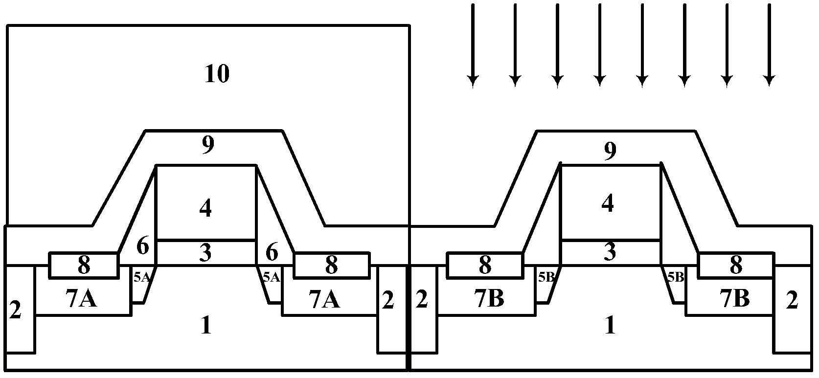
[0026] The following will refer to Figure 1 to Figure 3 A schematic cross-sectional view is used to describe in detail the steps of the CMOS device and its manufacturing method according to the present invention.

[0027] First, refer to Figure 4 as well as figure 1 , depositing a ...


PUM


Abstract

The invention discloses a CMOS device which comprises a first MOSFET, a second MOSFET, a first stress layer and a second stress layer. The second MOSFET is different from the first MOSFET in type. The first stress layer covers the first MOSFET and has first stress. The second stress layer covers the second MOSFET, and is provided with doping ions so as to have second stress which is different from the first stress. According to the CMOS device and a manufacturing method thereof, the method of partition ion injection is used for achieving a double-stress pad layer, photoetching / etching is needless for removing a tensile stress layer on a PMOS area or a pressure stress layer on an NMOS area, the technology is simplified, cost is lowered, and meanwhile the probable damage of the heat process of a sedimentation technology on the stress of the pad layer of the NMOS area or the stress of the pad layer of the PMOS area is also avoided.

Description

technical field [0001] The invention relates to a CMOS device and a manufacturing method thereof, in particular to a CMOS device and a manufacturing method thereof which change the properties of a stress layer through doping. Background technique [0002] Various stress engineering techniques have been widely used in sub-130nm technology and below technology generations. A central consideration for using stress engineering in CMOS technology is that PMOS and NMOS respond differently to different types of stress. Specifically, PMOS performance is improved by applying compressive stress to the channel region, while NMOS performance is improved by applying tensile stress to the channel region. [0003] One major approach involves the use of stress-inducing overlays. CVD silicon nitride is a common choice for the stress cap layer, and the magnitude and type of stress can be changed by adjusting deposition conditions such as temperature and frequency. Standard photolithography...

Claims


Application Information

Patent Timeline
IPC IPC(8): H01L27/092H01L21/8238
CPCH01L21/823807H01L29/165H01L29/7833H01L29/7843
Inventor 徐秋霞赵超许高博
Owner 锐立平芯微电子(广州)有限责任公司
Learn More