
Motor stator iron core pressing hydraulic machine

A technology for motor stators and hydraulic presses, which is applied in the manufacture of stator/rotor bodies, etc., can solve the problems affecting the centering and assembly accuracy of stator iron cores, high labor intensity of workers, and high production costs, so as to improve efficiency, press-fit quality, and save money. The effect of low resources and production costs

Inactive Publication Date: 2013-09-25
TIANJIN TIANDUAN PRESS CO LTD
View PDF5 Cites 8 Cited by
  • Summary
  • Abstract
  • Description
  • Claims
  • Application Information

AI Technical Summary

Problems solved by technology

[0003] At present, there are two commonly used processes for press-fitting the stator core of large and medium-sized vertical generators: one is to elongate the tightening screw of the stator core, and to compress the iron core with the help of a special pressure plate. To produce the pressing plate and lengthen the tensioning screw, the versatility is poor, the production cost of the tooling is high, and the labor intensity of the workers is high
The other is to calibrate the rib laminations with the help of the central column first, and use an umbrella-shaped gland for the pre-compression and total pressure of the iron core. For the convenience of installation, the umbrella-shaped gland needs to be lifted from the central column first, and then the iron core needs to be lifted after it is compressed. Umbrella-shaped gland, and the centering and assembly accuracy of the stator core are affected due to the multiple adjustments of the center column, which has a greater impact on the press-fitting quality of the generator core with smaller air gap requirements

Method used


Image

  • Motor stator iron core pressing hydraulic machine
  • Motor stator iron core pressing hydraulic machine
  • Motor stator iron core pressing hydraulic machine

Examples


Embodiment Construction

[0023] In order to further understand the invention content, characteristics and effects of the present invention, the following examples are given, and detailed descriptions are as follows in conjunction with the accompanying drawings:

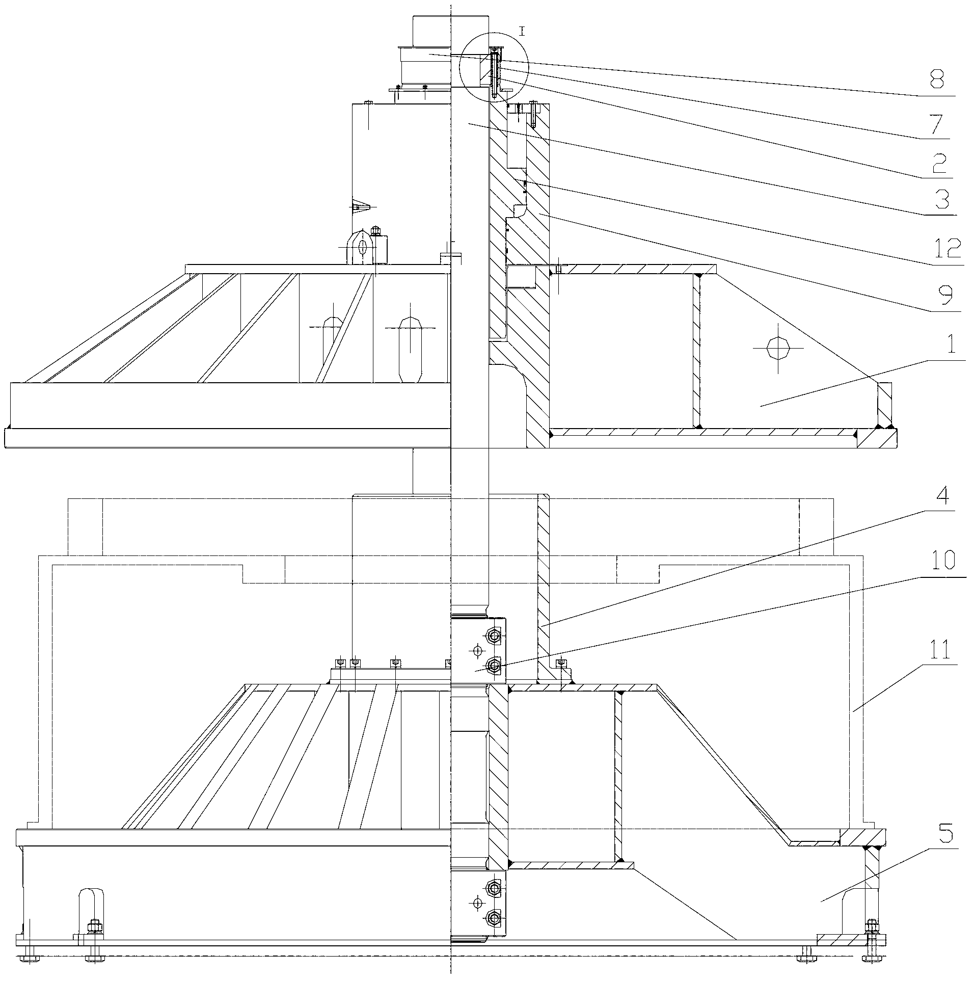
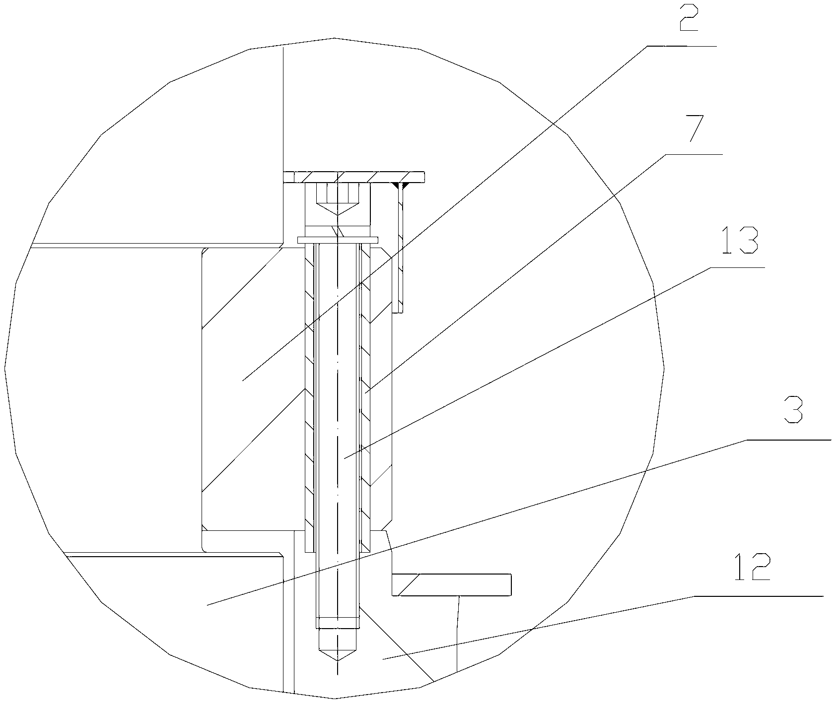
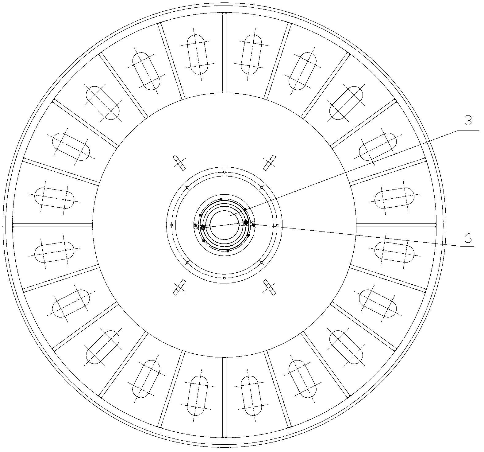
[0024] See Figure 1 ~ Figure 3 , a motor stator core press-fitting hydraulic machine, including an upper pressure plate 1, a tie rod 3, a limit sleeve 4, a lower pressure plate 5, a stopper 6, a sleeve 7, a cover 8, a main cylinder 9 and a mold base 11, the upper Both the pressure plate 1 and the lower pressure plate 5 are welded parts, which are welded by the upper ring, the lower ring, the rib plate, the support arm and the inner cylinder, among which the inner cylinder of the upper pressure plate 1 has a gap with the tie rod 3 Coordinated, the main ribs and the center are radially distributed in a ring, forming an umbrella structure. The lower platen 5 is fixed on the ground through T-shaped screws, and the upper ring of the lower platen...


PUM


Abstract

The invention relates to a motor stator iron core pressing hydraulic machine which comprises an upper pressing plate, a pull rod, a lower pressing plate and a main oil cylinder. The lower pressing plate is fixed on the ground through T shaped screws and is connected with a limit sleeve. The lower end of the pull rod in the limit sleeve is fixedly connected with the lower pressing plate through a locking nut. The upper part of the pull rod is fixedly connected with a piston rod of the main oil cylinder through a clamping ring. The main oil cylinder is fixedly connected with the upper pressing plate. The motor stator iron core pressing hydraulic machine has the advantages of simple structure and convenient installation and connection, two working stations can be arranged through division when the motor stator iron core pressing hydraulic machine is in use, the versatility is good, the tooling production cost is low, the labor amount is small, the resources are saved too, and the efficiency and pressing quality of the machine are effectively raised.

Description

technical field [0001] The invention belongs to the technical field of stator iron core pressing tools, in particular to a motor stator iron core pressing hydraulic machine. Background technique [0002] The application of wind energy, from windmills to wind power generation, proves the development of civilization and scientific progress in modern industry, and more wind power generation (stator core) is used in civil and commercial use. Based on the trend of development and utilization of new energy, the motor stator core press-fitting hydraulic machine was born in due course. It is mainly used for iron core press-fitting in the motor industry. Through the change of lamination tooling and fixtures, other stator cores that need to be stacked separately can be realized. It is generally applicable to the motor, energy and other industries. [0003] At present, there are two commonly used processes for press-fitting the stator core of large and medium-sized vertical generators...

Claims


Application Information

Patent Timeline
IPC IPC(8): H02K15/02
Inventor 王建超
Owner TIANJIN TIANDUAN PRESS CO LTD
Learn More