
Ultra-wide band impulsator

An ultra-wideband pulse and generator technology, applied in the electronic field, can solve the problem of not being able to obtain high repetition frequency ultra-wideband pulse signals at the same time, and achieve the effect of simple power supply

Active Publication Date: 2013-09-25
NAT SPACE SCI CENT CAS
View PDF4 Cites 12 Cited by
  • Summary
  • Abstract
  • Description
  • Claims
  • Application Information

AI Technical Summary

Problems solved by technology

[0007] The purpose of the present invention is to overcome the defect that the pulse generator in the prior art cannot simultaneously obtain ultra-wideband pulse signals with high repetition frequency and low ringing, thereby providing a kind of ultra-wideband pulse signal that can generate high repetition frequency and low ringing at the same time. Pulse generator for pulsed signals

Method used


Image

  • Ultra-wide band impulsator
  • Ultra-wide band impulsator
  • Ultra-wide band impulsator

Examples


Embodiment Construction

[0032] The present invention will be further described now in conjunction with accompanying drawing.

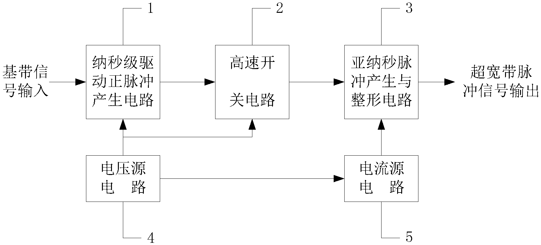
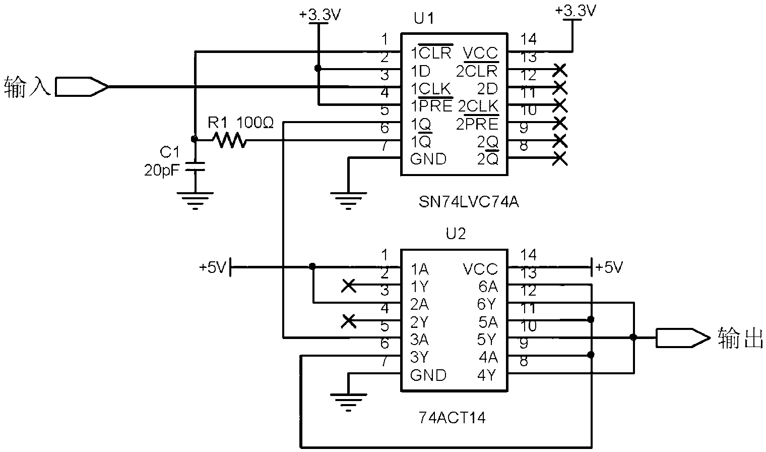
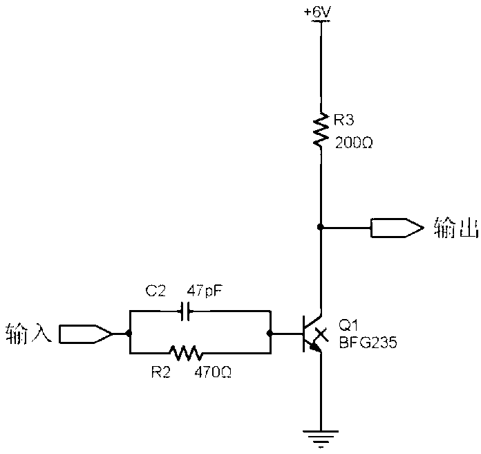
[0033] refer to figure 1 , The pulse generator of the present invention includes a nanosecond driving positive pulse generating circuit 1, a high-speed switching circuit 2, a sub-nanosecond pulse generating and shaping circuit 3, a voltage source circuit 4 and a current source circuit 5. Wherein, the nanosecond driving positive pulse generating circuit 1, the high-speed switching circuit 2 and the sub-nanosecond pulse generating and shaping circuit 3 are electrically connected in sequence, and the voltage source circuit 4 is respectively connected to the nanosecond driving positive pulse generating circuit 1, The high-speed switch circuit 2 is electrically connected to the current source circuit 5 , and the current source circuit 5 is also electrically connected to the sub-nanosecond pulse generating and shaping circuit 3 .

[0034] Each device in the pulse generator of the ...


PUM


Abstract

The invention discloses an ultra-wide band impulsator which comprises a nanosecond level driving positive impulse generating circuit, a speed-sensitive switch circuit, a subnanosecond impulse generating and shaping circuit, a voltage source circuit and a current source circuit. The nanosecond level driving positive impulse generating circuit converts impulse signals with random widths into nanosecond level narrow impulses with relatively fixed widths. The speed-sensitive switch circuit is switched into an on status from an off status under the driving of the narrow impulses, and the static power voltage of the input end of the subnanosecond impulse generating and shaping circuit is made to be reduced to be approach to zero rapidly. No signal is input in the input end of the subnanosecond impulse generating and shaping circuit in a static state, the shaping circuit is in a positive breakover status, and an output end has no signal output. When the speed-sensitive switch circuit is switched into the on status form the off status, the input end of the subnanosecond impulse generating and shaping circuit output currents, and the step recovery diode of the shaping circuit is changed into reversed breakover from positive breakover. After a period of time, the diode is changed into reversed cut-off from the reversed breakover, and the output end output currents. When the output end is connected with a load, the output end generates negative-polarity voltage impulses.

Description

technical field [0001] The invention relates to the field of electronics, in particular to an ultra-wideband pulse generator. Background technique [0002] Pulse ultra-wideband technology has many advantages such as large bandwidth, high capacity, low power consumption, precise positioning, simple structure, anti-interference, anti-multipath, small size, light weight, etc. It is very suitable for high-speed data transmission, precise positioning, etc. [0003] In the pulse UWB system, the pulse generator is not only the core unit of the transmitter, but also an important part of the receiver. The parameters of the pulse signal are directly related to the performance indicators of the system. Therefore, the development of a pulse generator that meets the requirements has always been is one of the hotspots of research. [0004] Pulse width is the determining factor of bandwidth and resolution. In order to meet certain application requirements, various sub-nanosecond pulse ge...

Claims


Application Information

Patent Timeline
Patent Type & Authority Applications(China)
IPC IPC(8): H03K3/017
Inventor 谢义方黄永辉熊蔚明
Owner NAT SPACE SCI CENT CAS
Learn More