Automatic clearance-removing double-worm speed reducer

A technology of double worm and reducer, which is applied in the direction of mechanical equipment, transmission devices, transmission device parts, etc., can solve the problems that the center distance cannot be adjusted, the processing quality and precision of machine tools are reduced, and solve the problems of low processing accuracy and high transmission accuracy Effect

Inactive Publication Date: 2013-10-02
济南若泰数控科技有限公司
View PDF8 Cites 8 Cited by
  • Summary
  • Abstract
  • Description
  • Claims
  • Application Information

AI Technical Summary

Problems solved by technology

[0003] In order to overcome the disadvantages of existing worm gear and worm drive reducers that the center distance cannot be adjusted, resulting in backlash and lowering of machine tool processing quality and precision, the present invention provides an automatic anti-backlash double worm reducer, which makes the two A worm is axially pressed against the worm gear to eliminate the gap, and the center distance between the worm and the worm wheel in this structure can be adjusted automatically. In addition, an electromagnetic brake is designed, and the reducer can realize complete self-locking when the worm is stationary to eliminate backlash. Improve the rigidity of the process system to the gap, thereby improving the transmission accuracy and rigidity of the machine tool, especially to improve the reverse rotation accuracy of the rotary shaft under the semi-closed-loop control system

Method used


Image

  • Automatic clearance-removing double-worm speed reducer
  • Automatic clearance-removing double-worm speed reducer

Examples


Embodiment Construction

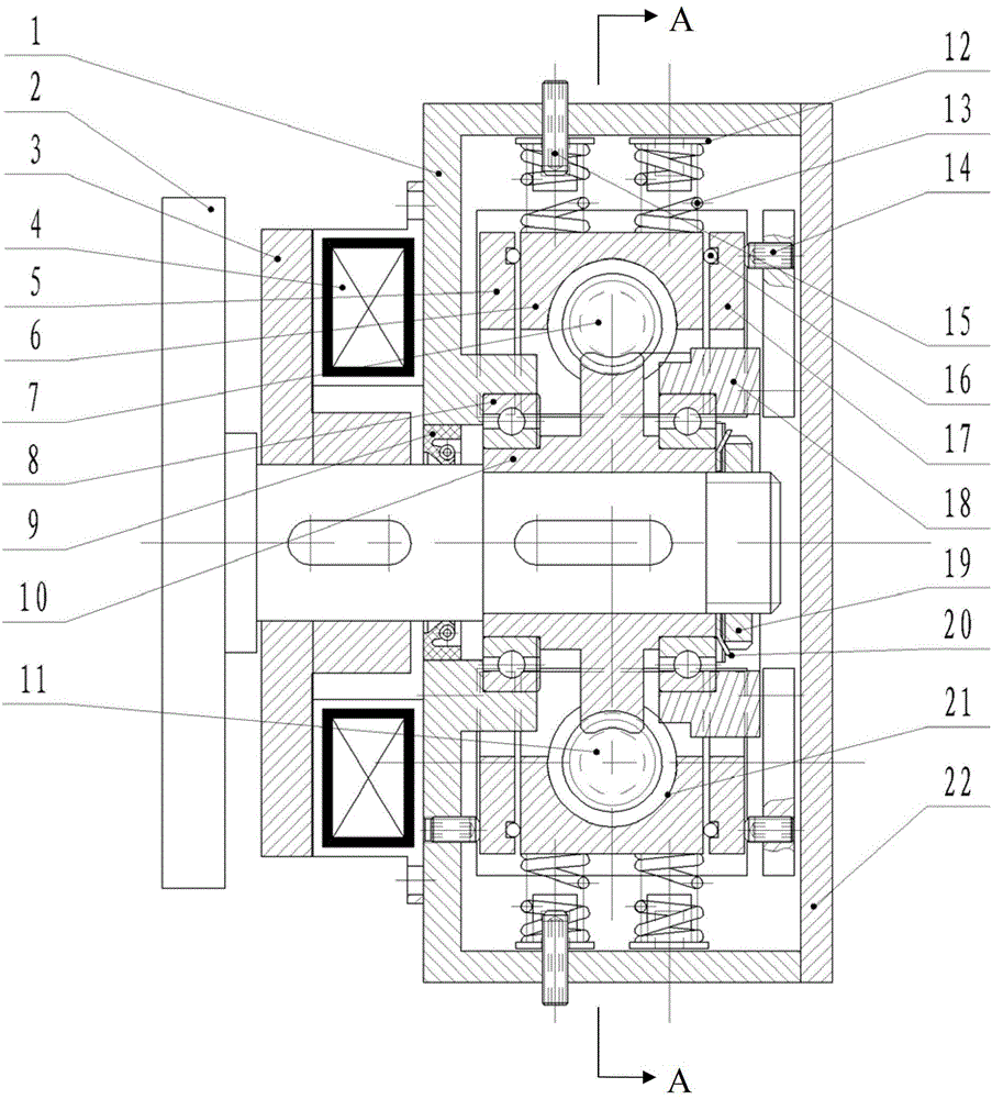
[0016] The present invention is described in detail below in conjunction with accompanying drawing

[0017] Such as figure 1 Shown, the upper worm (7) above is contained in a worm box (6) that can slide radially along the worm wheel (10), and the flexibility of sliding is guaranteed by balls (16). Four springs (13) are installed between the casing (1) and the worm box (6), which generate an elastic force pushing the worm box (6) toward the worm wheel (10), and can realize automatic alignment and automatic alignment during assembly. After finding the right position, use the adjusting screw (14) on the outside of the left adjustment plate (5) and the right adjustment plate (17) to ensure the correctness of the meshing position of the upper worm (7). The spring force-adjusting jackscrew (15) compresses the spring seat (12) and adjusts the force of the spring (13), thereby automatically adjusting the gap produced along with the rotation and wear of the worm wheel (10) and the upp...


PUM


Abstract

The invention discloses an automatic clearance-removing double-worm speed reducer which comprises a shell body, an upper worm, a lower worm, worm boxes, a worm gear, a flanged shaft and a brake disc. The upper side and the lower side of the worm gear are provided with the upper worm and the lower worm respectively, wherein the upper worm is meshed with the upper side of the worm gear, and the lower worm is meshed with lower side of the worm gear. The upper side and the lower side of the worm gear are structurally symmetrical. The worms are installed on the worm boxes which can slide in the radial direction along the worm gear through two conical roller bearings, one end of the upper worm and one end of the lower worm penetrate out of the worm boxes and are connected with elastic couplings, the right end shaft head of the flanged shaft is directly installed in a worm hole and is compressed with a round nut through a tab washer, an oil seal is arranged between the flanged shaft and the shell body, the brake disc is installed on the right head shaft head of the flanged shaft, and an electromagnetic coil is fixed on the shell body. When the worm gear and the worms are designed and assembled, zero clearance in theory is ensured, the automatic clearance-removing double-worm speed reducer can automatically adjust and remove the clearance which exists when the speed reducer is used, the problems that machining precision of a spindle of a four-shaft or five-shaft semi-closed loop control system is not high and the rigidity of process systems of some machine tools is not enough due to backlash at the present stage can be solved, and the automatic clearance-removing double-worm speed reducer is higher in transmission accuracy due to the adoption of the double worms.

Description

technical field [0001] The invention relates to a double worm reducer, in particular to an automatic anti-backlash double worm reducer which can automatically eliminate backlash and realize self-locking under certain circumstances. Background technique [0002] At present, the worm gear reducer adopted by the known numerical control equipment often adopts a structure of a worm and a worm wheel, and the center distance between the worm and the worm wheel cannot be adjusted. Due to manufacturing and assembly errors, generally there will be a large backlash, and the backlash angle of the better worm gear reducer at this stage is between 1' and 6', which has a huge impact on the machining accuracy of the workpiece. influences. If there is a gap of 3', the output shaft of the worm gear reducer is used as the B axis of the machine tool, so that the main shaft of the machine tool can get the movement of the swing head. When the distance from the tool edge on the main shaft to the ...

Claims


Application Information

Patent Timeline
Patent Type & Authority Applications(China)
IPC IPC(8): F16H1/22F16H57/12
Inventor 张鹏万恩宾
Owner 济南若泰数控科技有限公司
Why Eureka
Try Eureka