
Antenna phase center calibration system based on site insertion loss measurement

A technology of antenna phase center and insertion loss, applied in directions such as antenna radiation patterns, which can solve problems such as low accuracy and cumbersome process

Inactive Publication Date: 2013-10-02
NAT INST OF METROLOGY CHINA
View PDF4 Cites 26 Cited by
  • Summary
  • Abstract
  • Description
  • Claims
  • Application Information

AI Technical Summary

Problems solved by technology

[0005] In order to meet the demand for accurate measurement of the antenna parameters to be tested in an open field, and to overcome the shortcomings of the traditional phase center calibration method, such as low precision or cumbersome process, the purpose of this invention is to propose an antenna phase center calibration system based on site insertion loss measurement

Method used


Image

  • Antenna phase center calibration system based on site insertion loss measurement
  • Antenna phase center calibration system based on site insertion loss measurement
  • Antenna phase center calibration system based on site insertion loss measurement

Examples


Embodiment

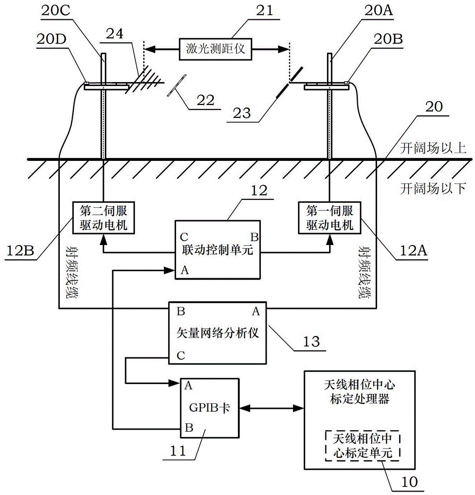
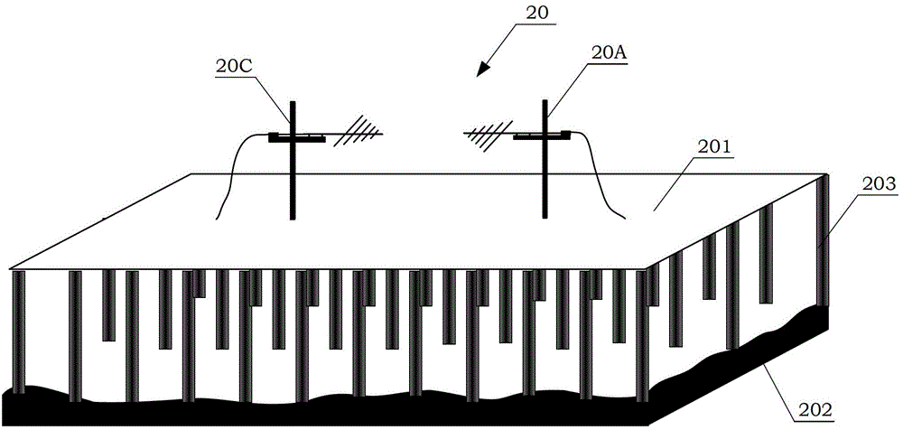
[0206] In this embodiment, two identical standard computable dipole antennas are selected for the reference antenna 23 and the antenna to be tested 24 . The specific model is the PRD standard calculable dipole developed and produced by the British National Physical Laboratory NPL, the resonant frequency is 900MHz, and the working frequency is 850MHz~950MHz. The phase center of the standard computable dipole antenna is precisely located at its geometric center. In order to achieve the verification purpose of the antenna phase center calibration and calibration system designed in the present invention, the geometric center of the antenna to be tested is selected as the phase center reference point, so its corresponding Theoretical values ​​of antenna phase center offsets x and z are both zero.

[0207] The actual test of site insertion loss is carried out in the open field of antenna calibration of China Institute of Metrology. The site is 60 meters long and 40 meters wide. The...


PUM


Abstract

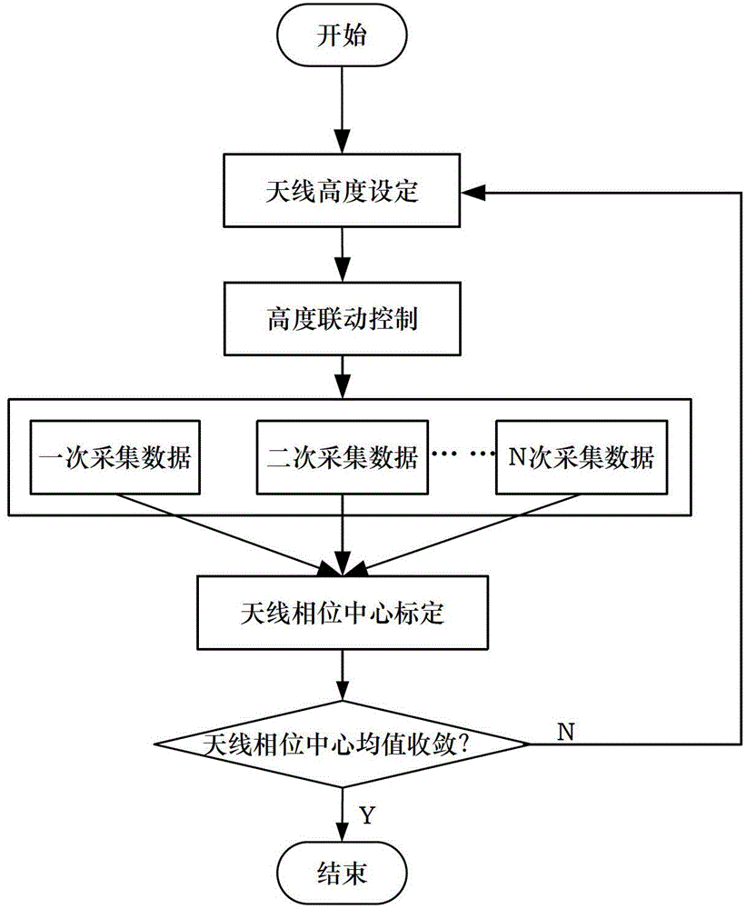
The invention discloses an antenna phase center calibration system based on site insertion loss measurement, which comprises an open site, a reference antenna, an antenna phase center calibration processor, a GPIB (General Purpose Interface Bus) card, a vector network analyzer and an antenna lifting component. When a to-be-measured antenna is subjected to phase center calibration, site insertion loss between the to-be-measured antenna and the reference antenna under the antenna heights is used twice, and an offset of an antenna phase center of the to-be-measured antenna relative to a reference point is acquired by a reflection wave path-reflection coefficient invariant strategy and an antenna phase center mean convergence criterion. The system aims at providing a calibration method for an open site antenna phase center. According to the system and the method, the antenna with the precise and known antenna phase center serves as the reference antenna, so that phase center calibration of the to-be-measured antenna is achieved; a phase center calibration mode depending on the reference antenna facilitates quantity value transmission of an antenna phase center parameter; and quantity value unification of the antenna parameter is achieved.

Description

technical field [0001] The invention belongs to the technical field of antenna measurement, and in particular relates to an antenna phase center calibration method and device. It is an antenna phase center calibration suitable for line antennas such as logarithmic periodic antennas and compound antennas. The system of the present invention utilizes site insertion loss measurement data on an open site, and obtains the offset of the antenna phase center relative to the reference point according to the "reflection wave path-reflection coefficient invariant strategy". Background technique [0002] The phase center of the antenna is an equivalent concept: after the electromagnetic wave radiated by the antenna leaves the antenna for a certain distance, its equiphase surface will be approximated as a sphere, and the center of the sphere is the (equivalent) phase center of the antenna . However, for most antennas, the far-field isophase surfaces are not strictly spherical, that is...

Claims


Application Information

Patent Timeline
IPC IPC(8): G01R29/10
Inventor 宋振飞王维龙谢鸣黄攀高小珣吴钒
Owner NAT INST OF METROLOGY CHINA
Learn More