Speed-control switch with kick device

A speed-regulating switch and jumping technology, which is applied in the direction of electric switches, electrical components, circuits, etc., can solve the problems of shortening the service life of switches, prone to twisting and shifting, and spring damage, so as to avoid arc burning of contacts, To avoid the effect of switch lifetime

Active Publication Date: 2013-10-02
KEDU ELECTRIC CO LTD
View PDF6 Cites 5 Cited by
  • Summary
  • Abstract
  • Description
  • Claims
  • Application Information

AI Technical Summary

Problems solved by technology

When the button assembly (2) is pressed, the first moving contact (5) first contacts the first static contact (51, 52), and as the movable frame (21) continues to move down, because the first static contact (51, 52), at this time, the first moving contact (5) will move upward relative to the movable frame (21), and compress the spring (53) in the cavity, resulting in the continuous increase of the elastic force of the spring (53) , while the first moving contact (5) will rub against the inner wall of the cavity when moving upward relative to the cavity, under the joint action of the elastic

Method used


Image

  • Speed-control switch with kick device
  • Speed-control switch with kick device
  • Speed-control switch with kick device

Examples


Embodiment Construction

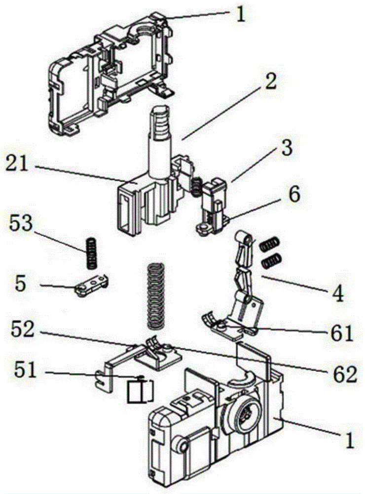
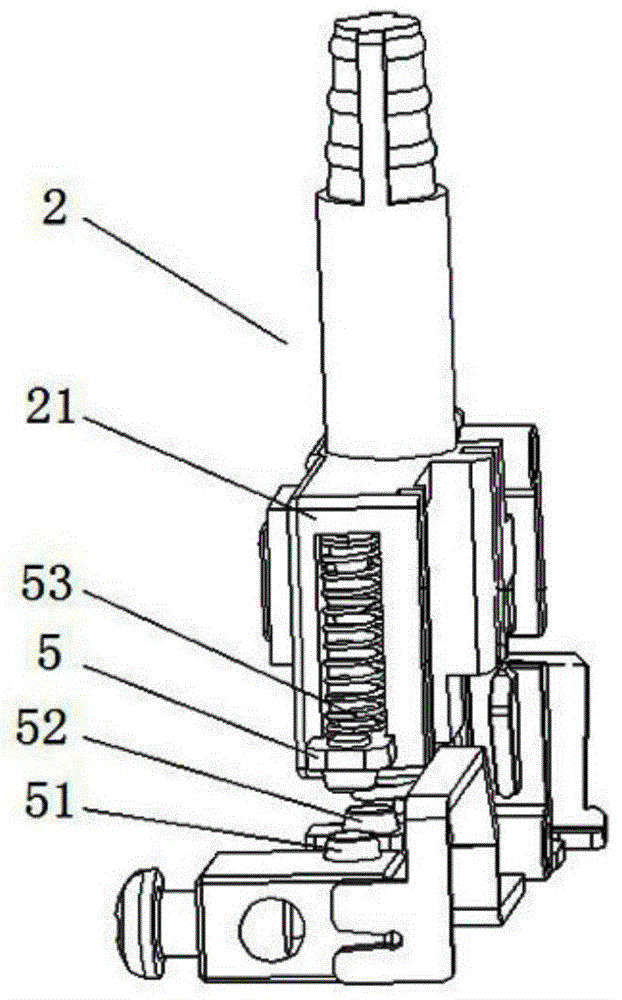
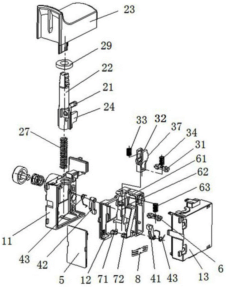
[0048] see image 3 , 10 , 11. The speed regulating switch with a kick device disclosed in the present invention includes a housing 1; and a button assembly 2 arranged inside the housing 1, a contact assembly driven by the button assembly 2, and a Cooperating with the button assembly 2, the second moving contact assembly 3 jumps up and down the locking block assembly 4. Wherein, the button assembly 2 is slidably arranged relative to the housing 1; the contact assembly includes a first contact assembly for controlling the on-off of the speed-regulating circuit board 5, and a first contact assembly for short-circuiting the speed-regulating circuit board. 5 to output the second contact assembly 3 of full voltage to the outside; the second contact assembly 3 includes the second moving contact assembly 3 driven by the button assembly 2 and the second static contact fixed relative to the housing 1 71, 72; the first contact assembly includes the first moving contact 6 driven by the...


PUM


Abstract

The invention discloses a speed-control switch with a kick device, which comprises a casing and a button component arranged at the inner part of the casing, a contact terminal component driven by the button component and a locking block component used for matching the button component to realize the up and down kick of the second moving contact component, wherein the contact terminal component comprises a first contact terminal component used for controlling the make-and-break of a speed regulation circuit board and a second contact terminal component used for short-connecting a speed regulation circuit of the speed regulation circuit board; a first moving contact in the first contact terminal component is connected with the casing through a spring; a protruding pole with the capability of pushing the first moving contact upward to compress the spring is arranged on the button component. After the first moving contact is contacted with a first fixed contact, the pressure between the first moving contact and the first fixed contact is constant and relatively static; the first moving contact and the first fixed contact can be in contact with each other tightly and are communicated well; the happening of the burning loss of the contact terminals by an electric arc when the speed regulation switch with the kick function communicates the speed regulation switch in the prior art is avoided; the shortening of the switch service life due to the frequent excessive compression of the spring connected with the first moving contact can be avoided.

Description

technical field [0001] The invention relates to the field of electric switches, in particular to a speed regulating switch with a kick device. Background technique [0002] Speed ​​control switches are used in electric tools such as electric drills, electric grinders, electric wrenches and electric screwdrivers. A traditional speed control switch mainly includes a housing, a button assembly, a contact assembly and a speed control circuit board arranged in the housing. Usually, the contact assembly includes two moving contacts and two static contacts. When working, press the button assembly, firstly drive the first moving contact to connect with the first static contact, turn on the speed regulating circuit board, at this time the electrical appliance starts to start; as the button assembly continues to be pressed down, the speed regulating circuit The board outputs a continuously changing voltage to the outside, and then realizes the speed regulation function; when the butt...

Claims


Application Information

Patent Timeline
IPC IPC(8): H01H13/02H01H13/12H01H13/28
Inventor 郑春开吴世明李子平
Owner KEDU ELECTRIC CO LTD
Why Eureka
Try Eureka