
Reaction chamber of dry plasma etcher

A reaction chamber and plasma technology, applied in discharge tubes, electrical components, circuits, etc., can solve the problems of poor atmosphere uniformity, short service life, and chamber pollution in the reaction chamber, and achieve improved plasma etching rate and high vacuum sealing And the effect of strong holding ability and large area

Inactive Publication Date: 2013-10-02
TDG MACHINERY TECH
View PDF12 Cites 3 Cited by
  • Summary
  • Abstract
  • Description
  • Claims
  • Application Information

AI Technical Summary

Problems solved by technology

[0006] In order to overcome the shortcomings of existing plasma etching equipment such as chamber pollution and damage, poor atmosphere uniformity in the reaction chamber, and short service life, the present invention provides a dry-process plasma etching device with a clean chamber, less pollution, and a long service life. The reaction chamber of the etching machine

Method used


Image

  • Reaction chamber of dry plasma etcher
  • Reaction chamber of dry plasma etcher
  • Reaction chamber of dry plasma etcher

Examples


Embodiment Construction

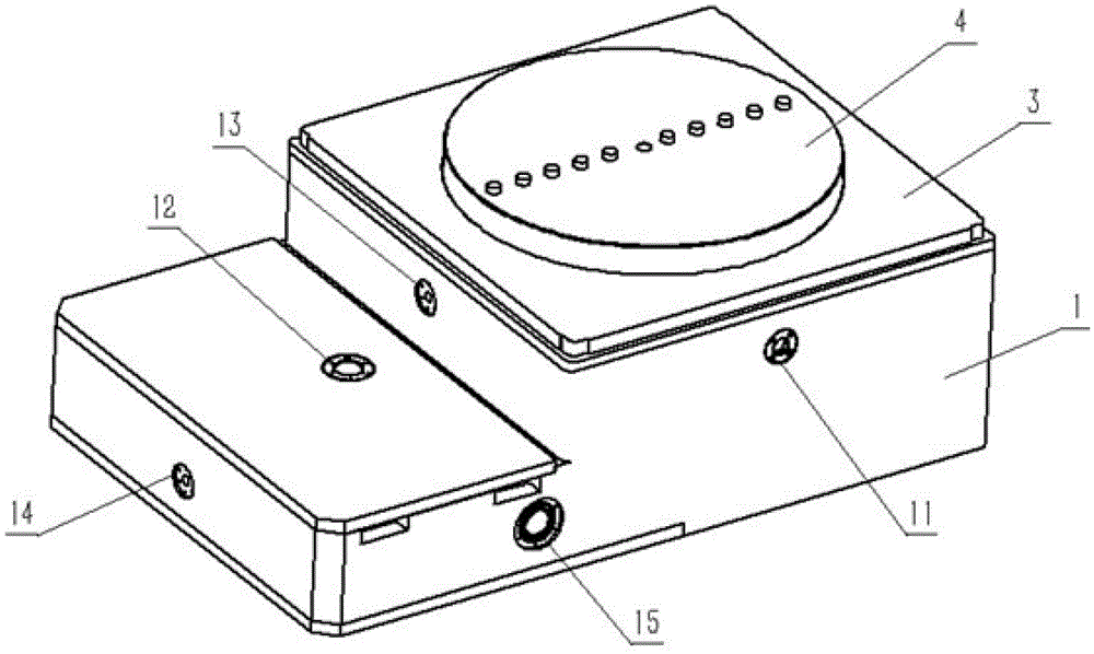
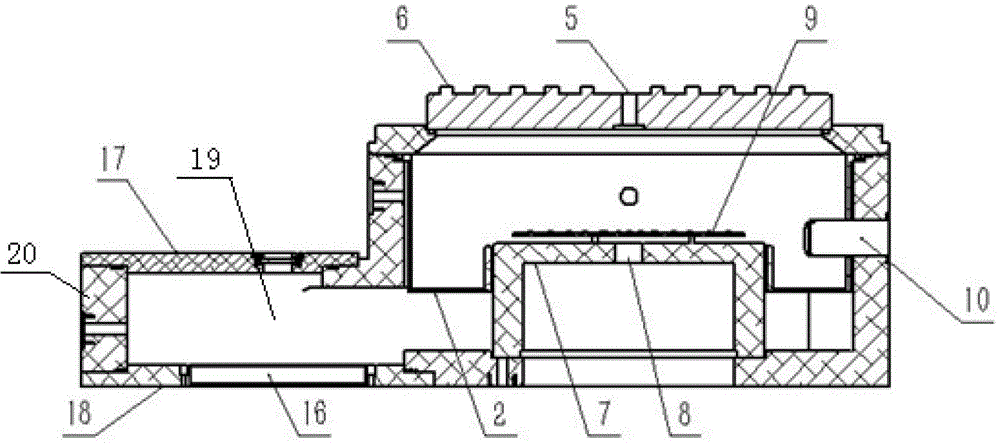
[0024] Such as figure 2 , 3 As shown, a reaction chamber of a dry plasma etching machine includes a cylindrical reaction chamber 1 and an upper cover covered on the reaction chamber 1, the central position of the upper cover is provided with an air inlet 5, and the side of the reaction chamber 1 The wall, bottom wall and upper cover form a reaction chamber 1, and the substrate to be etched is placed at the central position of the bottom wall of the reaction chamber 1, and the reaction chamber 1 is provided with a pick-up and delivery port 10 for taking and sending the substrate;

[0025] The reaction chamber 1 is provided with a uniform flow liner 2 adapted thereto. The uniform flow liner 2 includes a cylindrical body 21. The body 21 is provided with a transfer hole 25 corresponding to the sheet feeding port 10. The bottom of the body 21 is provided with a There is a ring-shaped bottom plate 22 extending inward, which matches the position of the substrate to be etched, and u...


PUM

PropertyMeasurementUnit
Widthaaaaaaaaaa

Abstract

A reaction chamber of a dry plasma etcher comprises a cylindrical reaction chamber and an upper cover covering the cylindrical reaction chamber, wherein an air inlet hole is formed in the center of the upper cover, the cylindrical reaction chamber is formed by a side wall, a bottom wall and the upper cover, a substrate to be etched is placed in the center of the bottom wall of the reaction chamber, and a substrate picking and delivering port for picking up and delivering the substrate is formed in the reaction chamber; a uniform-flow inner lining matched with the reaction chamber is arranged in the reaction chamber and comprises a cylindrical main body, a transmission hole corresponding to the substrate picking and delivering port is formed in the main body, a circle of ring-shaped baseplate extending inwards is arranged at the bottom of the main body and corresponds to the substrate to be etched in position, and uniform-flow slotted holes are uniformly distributed in the ring-shaped baseplate; a mounting flange connected with the reaction chamber is arranged at the top of the main body and a sealing groove is formed between the mounting flange and the reaction chamber. The reaction chamber has the advantages of clean cavity, little pollution, good atmosphere and uniformity in the chamber and long service life.

Description

technical field [0001] The invention relates to the technical field of plasma etching, in particular to a reaction chamber of a dry plasma etching machine. Background technique [0002] Etching is an important process in the manufacturing process of semiconductors, microelectronics and LEDs. Etching is the process of selectively removing unnecessary materials from the surface of silicon wafers or sapphire substrates by chemical or physical methods. With the improvement of the integration level of semiconductor devices, the line width of semiconductor devices is getting smaller and smaller, the control of critical dimensions is becoming more and more important, and the requirements for etching processes are also getting higher and higher. In terms of process, etching can be divided into wet etching and dry etching. Dry etching is plasma etching. Usually, an etching gas is introduced into a plasma processing device, and the etching gas is ionized to form a plasma, and the waf...

Claims


Application Information

Patent Timeline
IPC IPC(8): H01J37/32
Inventor 张钦亮平志韩苏静洪王谟俞敏人
Owner TDG MACHINERY TECH
Learn More