Low voltage draw-out switchgear

A low-voltage draw-out switchgear technology, applied in draw-out switchgear, switchgear, switchgear parts, etc. The effect of overhaul or maintenance, prevention of arc fault, and loss reduction

Inactive Publication Date: 2013-10-02
厦门市聚力电力设备有限公司
View PDF5 Cites 0 Cited by
  • Summary
  • Abstract
  • Description
  • Claims
  • Application Information

AI Technical Summary

Problems solved by technology

[0003] The current low-voltage withdrawable switchgear cabinet layout is not reasonable, because the horizontal bus room of the equipment is set on the upper part of the rear half of the cabinet, the vertical bus room is set under the horizontal bus room, and the cable room and the functional unit room are arranged side by side. In the lower part of the cabinet, the space that can be effectively used in the cabinet is small, and it is impossible to install more equipment in the existing space
[0004] At present, most of the low-voltage withdrawable switchgears on the market do not have the real-time temperature monitoring function. When the operating temperature of the equipment is too high, the user cannot obtain the temperature information at the first time, so as to take some countermeasures, so some users bring inconvenient
[0005] Moreover, the outlets of the drawers in the functional unit rooms of the low-voltage withdrawable switchgears on the market are mostly installed on the side of the drawers. This structure has the following disadvantages: the installation efficiency of the outlets is low, the cabinet occupies a large space, and the cable time is small. It is difficult for construction workers to operate during the cable connection process

Method used


Image

  • Low voltage draw-out switchgear
  • Low voltage draw-out switchgear

Examples


Embodiment Construction

[0024] The present invention will be further described in conjunction with the accompanying drawings and specific embodiments.

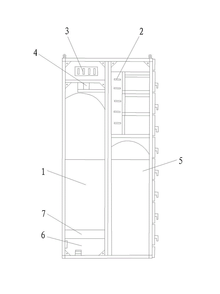
[0025] As a specific example, such as figure 1 and figure 2 As shown, a low-voltage withdrawable switchgear includes a cabinet, and the cabinet includes a cable room 1, a horizontal bus room 2, a vertical bus room 3, a small bus room 4, a functional unit room 5 and a neutral ground bus room 6 , the horizontal bus room 2 is arranged on the upper part of the front half of the cabinet, the functional unit room 5 is arranged on the lower part of the front half of the cabinet, and is located below the horizontal bus room 2, the vertical bus room 3 and the small bus room 4 Arranged side by side at the upper part of the rear half of the cabinet, the cable chamber 1 is arranged at the lower part of the rear half of the cabinet, the neutral ground bus chamber 6 is disposed below the cable chamber 1, the cable chamber 1 and the neutral ground An electrical ...


PUM


Abstract

The invention relates to the field of medium and low voltage electrical equipment manufacture, and discloses a low voltage draw-out switchgear, which includes a cabinet body, wherein the cabinet body includes a cable chamber, a horizontal bus chamber, a vertical bus chamber, a small bus chamber, a functional unit chamber and a neutral grounding bus chamber; the horizontal bus chamber is arranged at the upper part of the front half side of the cabinet body; the functional unit chamber is arranged at the lower part of the front half side of the cabinet body, and is positioned below the horizontal bus chamber; the vertical bus chamber and the small bus chamber are arranged at the upper part of the rear half side of the cabinet in parallel; the cable chamber is arranged at the lower part of the rear half side of the cabinet body; the neutral grounding bus chamber is arranged below the cable chamber; an electric appliance mounting chamber is arranged between the cable chamber and the neutral grounding bus chamber. The cabinet body of the low voltage draw-out switchgear is of a wholly assembled structure, and is convenient to expand; arrangement of all parts of the cabinet body is changed; the electric appliance mounting chamber is isolated between the cable chamber and the neutral grounding bus chamber, so the operation process of equipment can be monitored in real time and an alarm can be send out.

Description

technical field [0001] The invention relates to the field of medium and low-voltage electrical equipment manufacturing, in particular to a withdrawable low-voltage switchgear. Background technique [0002] Low-voltage switchgear is a very important electrical equipment in industry. It is suitable for providing high-reliability low-voltage power distribution systems and motor control systems that meet the requirements of continuous power supply in electric power, metallurgy, petrochemical and other industries. It is mainly used as power distribution in the three-phase AC frequency of 50 (60) HZ, rated working voltage of 380 (400 / 600) V, rated current of 4000 A and below, centralized control of motors, and reactive power compensation. Low-voltage complete power distribution equipment. [0003] The current low-voltage withdrawable switchgear cabinet layout is not reasonable, because the horizontal bus room of the equipment is set on the upper part of the rear half of the cabin...

Claims


Application Information

Patent Timeline
Patent Type & Authority Applications(China)
IPC IPC(8): H02B11/173H02B11/02H02B1/30H02B1/20H02B11/133
Inventor 王银鑫
Owner 厦门市聚力电力设备有限公司
Why Eureka
Try Eureka