Optical module high and low temperature test system

An optical module testing and testing system technology, applied in the field of optical communication, can solve the problems of inconvenience that only one product can be tested at a time, the high cost of optical module testing, and the large volume of the low temperature box, so as to shorten the test waiting time. , Improve test efficiency, small size effect

Active Publication Date: 2017-08-11
DALIAN CANGLONG OPTOELECTRONICS TECH
View PDF5 Cites 0 Cited by
  • Summary
  • Abstract
  • Description
  • Claims
  • Application Information

AI Technical Summary

Problems solved by technology

At present, the high-temperature test of optical modules is usually carried out on a heating table, and the low-temperature test is completed in a low-temperature box. The commonly used low-temperature test system is modified by the module manufacturer. Inconvenient, only one product can be tested at a time, and due to the long cooling time, the waiting time of the module from normal temperature to low temperature test is also relatively long, it takes about 15 minutes of pre-cooling to complete the 5-minute test, and the test efficiency is low
At present, there is no high and low temperature testing system dedicated to optical modules. Therefore, the high and low temperature testing of optical modules has always been the bottleneck of optical module production, and the cooling equipment on the market is expensive, resulting in high testing costs for optical modules.

Method used


Image

  • Optical module high and low temperature test system
  • Optical module high and low temperature test system
  • Optical module high and low temperature test system

Examples


Embodiment 1

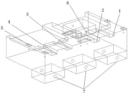
[0025] Such as figure 1 In the shown optical module test bench, an optical module test unit is arranged on the test bench, and the optical module test unit includes one XFP test unit and one SFP test unit. The XFP unit includes 1 XFP test slot 2 and 1 XFP pre-cooling slot 1. The depth of the XFP test slot 2 is half of the height of the XFP module, and its width is controlled within the positive tolerance of the XFP module width within 2mm, ensuring that the module The contact area with the test slot is the largest to achieve the best cooling effect, and it can perfectly cooperate with the Molex interface on the circuit board above. The width of XFP pre-cooling slot 1 is the same as that of XFP test slot 2, and its depth is 2mm deeper than that of XFP test slot 2, which can pre-cool the modules well. The SFP test unit includes SFP test tank 4 and SFP pre-cooling tank 3. The depth of SFP test tank 4 is half of the height of the SFP module, and its width is controlled within the...

Embodiment 2

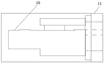
[0038] The structure of the optical module high and low temperature test system in this embodiment is basically the same as that in Embodiment 1, the difference is that: Figure 5 , 6As shown, a cooling pipeline 15 is added inside the test bench 10, and the cooling pipeline 15 is located below the optical module test unit. 17 is located inside the test platform 10 . During the low-temperature test, liquid nitrogen is input into the refrigeration pipeline 15 through the liquid nitrogen access pipeline 14, and the liquid nitrogen is discharged from the air outlet 17 through the internal circulation pipeline from the air inlet 16. Since the refrigeration pipeline 15 is located on the test bench 10, the optical module test It is directly below the unit, so it can directly cool the test unit to achieve the purpose of rapid cooling.

[0039] The invention has simple design, low cost, and is compatible with high and low temperature tests of XFP and SFP / SFP+. By setting the pre-cool...


PUM


Abstract

The invention belongs to the field of optical communication, and in particular relates to an optical module testing system. A high and low temperature test system for optical modules is proposed, including a test bench, a test door, and a cabinet. The test bench and the test door are fixedly assembled and placed in the cabinet. The test door and the cabinet are sealed and assembled. In the module testing unit, an operation port is opened on the test door at a position facing the optical module testing unit, and a temperature control system and a refrigeration system are arranged in the box. The present invention has simple design, low cost, and is compatible with high and low temperature tests of XFP and SFP / SFP+. A pre-cooling tank is installed adjacent to the XFP and SFP test tanks to pre-cool in advance, greatly saving test waiting time and improving test efficiency. It solves the bottleneck of low temperature testing of optical modules and fills a gap in the current high and low temperature testing system of optical modules.

Description

technical field [0001] The invention belongs to the field of optical communication, and in particular relates to an optical module testing system. [0002] technical background [0003] Optical transceiver integrated module (XFP, SFP, SFP+, SFF, etc.) is an indispensable core component in the optical fiber access network. The optical transceiver integrated module (hereinafter referred to as the optical module) is an optoelectronic system that realizes photoelectric and electro-optical conversion and has an independent transmitting drive and receiving amplifier circuit. Plug and unplug the product. Optical modules play the role of optical repeaters in optical fiber long-distance communication. Optical module testing is the premise to ensure product performance and quality, whether complete and accurate testing can directly determine product quality and cost. There are many testing procedures for optical modules, including initial test at room temperature, final test, high t...

Claims


Application Information

Patent Timeline
Patent Type & Authority Patents(China)
IPC IPC(8): H04B10/07
Inventor 袁家勇张彩
Owner DALIAN CANGLONG OPTOELECTRONICS TECH
Why Eureka
Try Eureka