Electronic equipment with asymmetrical heat dissipation structure

A technology of heat dissipation structure and electronic equipment, applied in the direction of cooling/ventilation/heating transformation, etc., can solve the problems of large dielectric loss coefficient, signal transmission loss, signal loss, etc., and achieve large effective heat dissipation area, large welding area, and efficient heat dissipation Effect

Active Publication Date: 2013-10-02
DONGGUAN SHENGYI ELECTRONICS
View PDF3 Cites 7 Cited by
  • Summary
  • Abstract
  • Description
  • Claims
  • Application Information

AI Technical Summary

Problems solved by technology

[0003] The conventional PCB solution is to use heat-conducting plates and dense heat dissipation holes for high-power device areas, but the heat conduction effect of heat-conducting plates and dense heat-dissipating holes is not good, and the dielectric loss coefficient of the plates is large, resulting in poor heat dissipation in the area of ​​micro high-power devices. , Signal transmission loss and distortion are serious, which affects the signal quality of communication products
[0004] Another solution to heat-dissipating PCBs is to use laminated embedding or embedding heat-conducting materials as heat-conducting channels in the high-power device area.

Method used


Image

  • Electronic equipment with asymmetrical heat dissipation structure
  • Electronic equipment with asymmetrical heat dissipation structure

Examples


Embodiment Construction

[0022] In order to further illustrate the technical means adopted by the present invention and its effects, the following describes in detail in conjunction with preferred embodiments of the present invention and accompanying drawings.

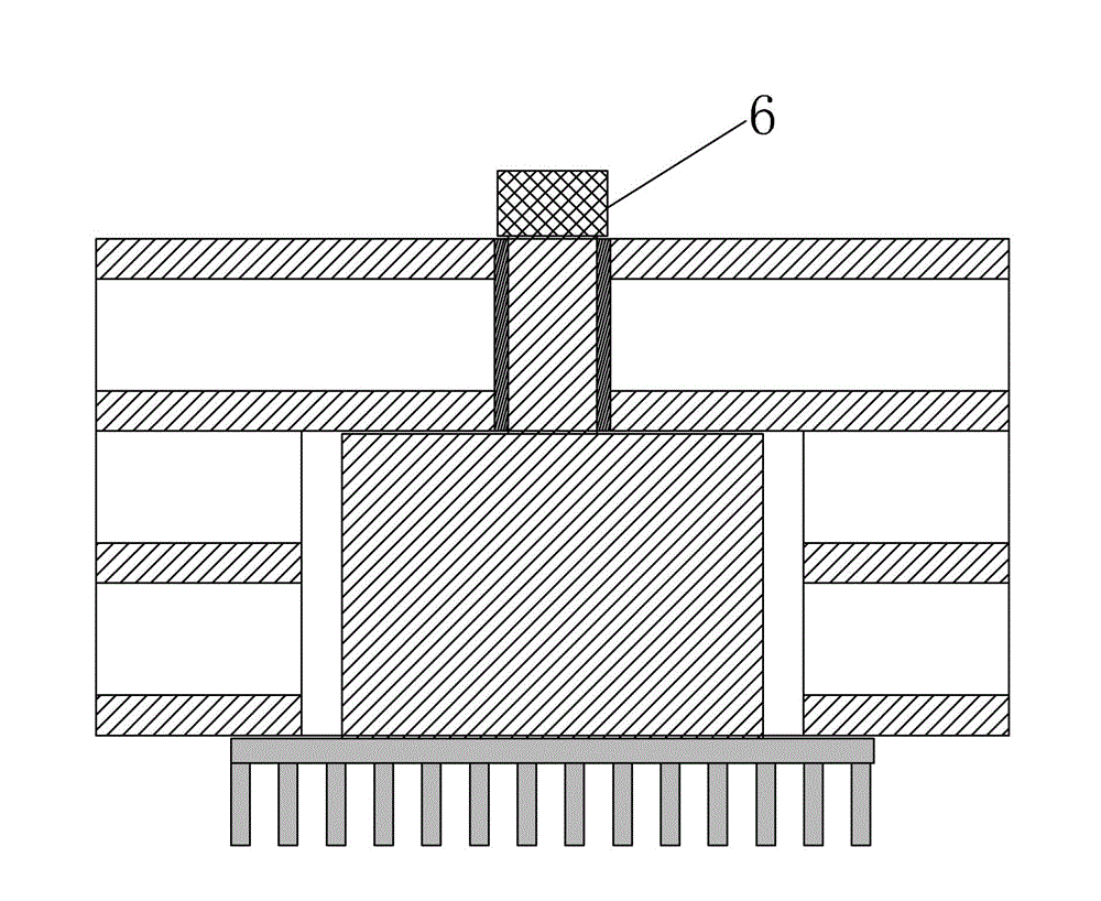
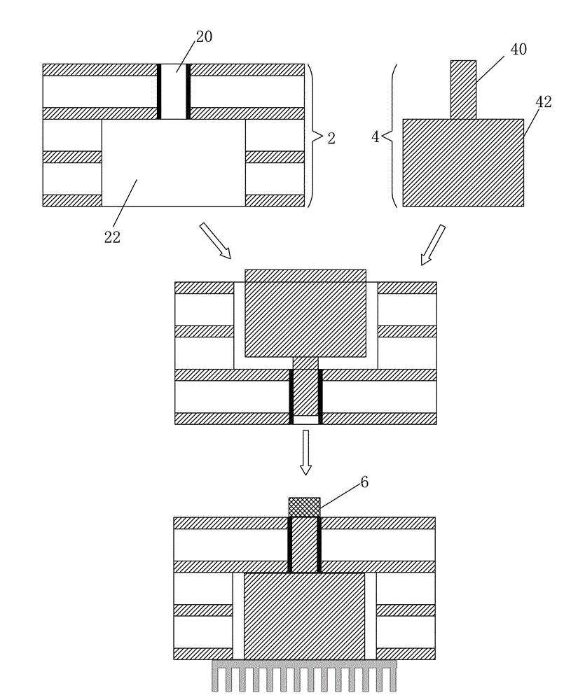
[0023] see figure 1 and figure 2 , the present invention provides an electronic device with an asymmetric heat dissipation structure, comprising: a PCB substrate 2, a heat-conducting metal core 4 installed in the PCB substrate 2, and a high-power micro-device 6 installed on the heat-conducting metal core 4, the heat-conducting The metal core 4 includes a base 42 and a protrusion 40 extending from the base 42. The size of the protrusion 40 is set corresponding to the micro high-power device 6. The size of the base 42 is larger than the size of the protrusion 40. The micro high-power device 6 is mounted on the raised portion 40 .

[0024] The PCB substrate 2 is provided with a first groove 20 corresponding to the protruding portion 40, and a ...


PUM

PropertyMeasurementUnit
Diameteraaaaaaaaaa

Abstract

The invention provides electronic equipment with an asymmetrical heat dissipation structure, which comprises a PCB (printed circuit board) substrate, a heat conducting metal core installed in the PCB substrate, and a miniature high-power device installed on the heat conducting metal core, wherein the heat conducting metal core comprises a base part and a protruding part extending from the base part, the size of the protruding part corresponds to that of the miniature high-power device, the size of the base part is greater than that of the protruding part, and the miniature high-power device is installed on the protruding part. The electronic equipment provided by the invention realizes effective heat dissipation of the high-power miniature device through the asymmetrical heat conducting metal core installed in a first slot part and a second slot part; the surface area of the PCB substrate is not occupied, an intensive circuit pattern design around the high-power miniature device is not affected, and the flexibility is high; and the effective heat dissipation area of the asymmetrical heat conducting metal core is large, and a function of effective heat dissipation of a partial micro area of the PCB substrate is realized.

Description

technical field [0001] The invention relates to the field of heat dissipation of electronic equipment, in particular to an electronic equipment with an asymmetric heat dissipation structure. Background technique [0002] At present, there is a design for high-end wireless communication in the printed circuit board (PCB) industry: one side of the PCB is designed with miniature high-power devices (≤2mm), and there are denser circuit graphics designs around the devices, which require communication with the inner layer; On the other side of the PCB corresponding to the micro high-power device area, the graphics design density is not high, but heat sinks need to be mounted to dissipate the large amount of heat generated by the micro high-power devices. [0003] The conventional PCB solution is to use heat-conducting plates and dense heat dissipation holes for high-power device areas, but the heat conduction effect of heat-conducting plates and dense heat-dissipating holes is not ...

Claims


Application Information

Patent Timeline
IPC IPC(8): H05K7/20
Inventor 李民善纪成光杜红兵吕红刚
Owner DONGGUAN SHENGYI ELECTRONICS
Why Eureka
Try Eureka