Supercharge Your Innovation With Domain-Expert AI Agents!

Horizontal feeding mechanism for the front conveyor belt for punching bearing blanks

A technology of conveyor belt and blank, applied in the field of mechanical bar material conveying structure, can solve the problems of small focus point, small entry point, long feeding rod, etc., and achieve the effect of compact and reasonable structure and high work efficiency

Inactive Publication Date: 2016-08-10
永安市银亨机械有限公司 +1
View PDF4 Cites 0 Cited by
  • Summary
  • Abstract
  • Description
  • Claims
  • Application Information

AI Technical Summary

Problems solved by technology

[0003] The disadvantage of this structure is that the lever is long, the horizontal position of the second cylinder occupies a large space, and the lever can only be inserted between the first and second bars with a small angle and small space deflection, and the entry point is small and the force point is small. When there is a small error in the space size of the bar, there is an error in the entry point and the material is shifted intermittently. At the same time, there is a problem of synchronization deviation between the two cylinders, and failures often occur.

Method used


Image

  • Horizontal feeding mechanism for the front conveyor belt for punching bearing blanks
  • Horizontal feeding mechanism for the front conveyor belt for punching bearing blanks
  • Horizontal feeding mechanism for the front conveyor belt for punching bearing blanks

Examples


Embodiment Construction

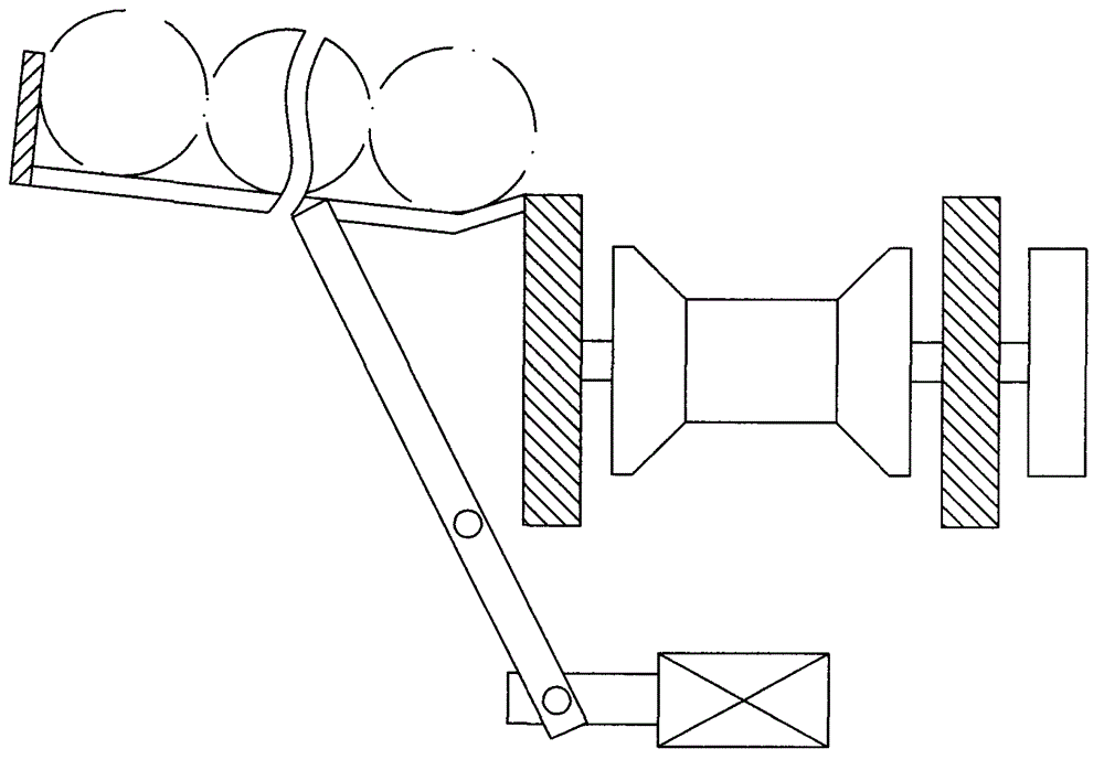
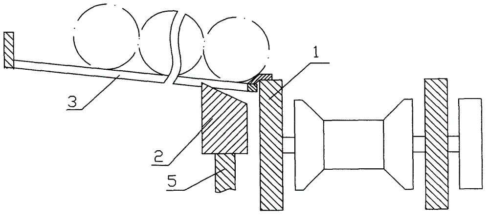
[0011] The structure of the present invention comprises feeding frame 3, cylinder 11, is characterized in that: the long steel plate wall 1 outer side of conveyer belt is provided with longitudinal bracket parallelly, and the two ends of longitudinal beam 7 of longitudinal bracket respectively fix a short square tube cover 6, short square tube cover 6. A square tubular elevating rod 5 is fitted in the internal movement. The upper end of the elevating rod 5 is fixed with a push rod block 2 with a lateral width smaller than the diameter of the bar material. There is a U-shaped fork with an opening downward, and a pin shaft is fixed in the center holes on both sides of the U-shaped fork, and the pin shaft is moved up to fit the pulley 8; the center point of the longitudinal beam 7 is fixed to a cylinder 11 downward, and a cylinder 11 is fixed on the end of the piston. The transverse plate 13 is symmetrically provided with two through holes on the transverse plate 13, and the longi...


PUM


Abstract

The invention relates to a transverse feeding mechanism for a bearing blank punching preposed conveyor belt. The transverse feeding mechanism comprises a feeding frame and a cylinder, and is characterized in that short square pipe sleeves are respectively fixed at two ends of a longitudinal beam of a longitudinal support, which is arranged on the outer side of a long steel plate wall of the conveyor belt in parallel, bar ejection blocks are fixedly arranged at the upper end parts of lifting rods which are sheathed in the short square pipe sleeves by movable fit, inclined planes which are inclined to the inner side are arranged on the upper surfaces of the bar ejection blocks, and pulleys are sheathed in U-shaped forks at the lower end parts of the lifting rods; a cylinder is downwards fixed in the position of a center point of the longitudinal beam, a transverse plate is fixed at the end of a piston, pivot rods are respectively fixed between the cylinder and the lifting rods on the two sides in the longitudinal beam, the middle parts of two levers are respectively articulated with the lower end parts of the two pivot rods, the inner end of each lever is articulated with the transverse plate of a piston rod of the cylinder through a transition plate, and the other end of each lever is close to the pulley of the lifting rod; and the inclined plane of the bar ejection block of each lifting rod is close to the lower circumferential surface of a first bar material to be stirred. The transverse feeding mechanism has the advantages that the cylinder can synchronously drive two material ejection blocks to lift through the levers, and inclined planes on the material ejection blocks can lift the first bar material to enable the first bar material to roll into the conveyor belt.

Description

Technical field: [0001] The invention relates to a mechanical bar material conveying structure, in particular to a horizontal feeding mechanism for a bearing blank punching front conveyor belt. Background technique: [0002] In the processing and production of bearings, firstly, the 6-7 meters of bearing steel bars are heated in the induction coil of the intermediate frequency furnace through the conveying device, and then enter the punching machine for cutting and cutting. The structure of the conveyor belt is that several concave rollers are evenly distributed between the long steel plate walls on both sides. Realize the longitudinal movement of the bar. The two sides of the conveyor belt are respectively equipped with a feeding mechanism and a material returning mechanism. Feeding the conveyor belt relies on a parallel feeding mechanism with a length of 6 to 7 meters on the side of the steel plate wall, and its feeding form is horizontal feeding. The feeding mechanism ...

Claims


Application Information

Patent Timeline
Patent Type & Authority Patents(China)
IPC IPC(8): B65G47/04
Inventor 卢健清
Owner 永安市银亨机械有限公司
Features
  • R&D
  • Intellectual Property
  • Life Sciences
  • Materials
  • Tech Scout
  • Unparalleled Data Quality
  • Higher Quality Content
  • 60% Fewer Hallucinations
Learn More