Eureka AIR delivers breakthrough ideas for toughest innovation challenges, trusted by R&D personnel around the world.

Zone melting and directional solidifying method used for volatile element alloy

A technology of directional solidification and regional melting, which is applied in the direction of self-regional melting method, chemical instruments and methods, and improvement of process efficiency. It can solve the problem that the actual composition of the alloy deviates from the design composition, the distribution of the axial composition is not uniform, and the alloy loses the design functionality. and other problems, to achieve the effect of uniform distribution of axial components, large practical application value, and reduced loss

Inactive Publication Date: 2013-10-09
SHANGHAI JIAO TONG UNIV
View PDF5 Cites 9 Cited by
  • Summary
  • Abstract
  • Description
  • Claims
  • Application Information

AI Technical Summary

Problems solved by technology

[0002] Preventing the volatilization and burning loss of volatile elements during the solidification process has always been the core problem in the preparation of alloy materials, especially in the slow directional solidification process of functional materials, the volatilization and burning loss of these volatile elements will lead to the actual composition of the alloy Deviating from the design composition, the alloy will eventually lose its original design functionality
[0003] As far as functional materials are concerned, their functionality often only exists in specific crystal orientations, and the traditional Bridgeman method, which completely melts the material and then directional solidifies, easily leads to uneven distribution of axial components, so it needs to pass Advanced methods such as regional melting and directional solidification are used to achieve
According to the characteristics of directional solidification, it can be known that the slower the crystal growth rate, the easier it is to obtain highly preferentially oriented crystals, and at the same time, the loss of volatile elements is also greatly increased.

Method used


Image

  • Zone melting and directional solidifying method used for volatile element alloy

Examples


example 1

[0028] Example 1: Ni 50 mn 34 In 16 (at.%) alloy

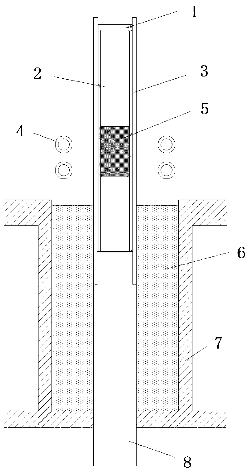
[0029] The present invention will be further described below in conjunction with the longitudinal sectional schematic diagram of the directional solidification device used in the present invention. The directional solidification device includes: induction coil 4 , liquid metal 6 , circulating cooling water 7 , and pull rod 8 . In addition, the schematic diagram also includes: molten slag 1 , alloy initial rod 2 , directional solidification crucible 3 , and alloy melting zone 5 .

[0030] The working process of the above-mentioned directional solidification device is as follows: the initial alloy rod 2 is vertically placed in the directional solidification crucible 3, the gap between the initial alloy rod 2 and the directional solidification crucible 3 is filled with a slagging agent, and the heating by the induction coil 4 , so that the initial alloy bar 2 area is melted to form an alloy melting zone 5, and the slagging ag...

example 2

[0038] Example 2: La(Fe 0.86 Si 0.14 )13 (at.%) alloy

[0039] La(Fe 0.86 Si 0.14 ) 13 (at.%) alloy exhaustive zone melting directional solidification steps are as follows:

[0040] 1. Alloy La(Fe 0.86 Si 0.14 ) 13 (at.%). The raw materials for configuring the alloy are: pure lanthanum, pure iron, and pure silicon. The purity of the above three raw materials is 99% (by mass percentage), and the total weight of the alloy is 40g. Since the element La in the alloy is volatile, the proportion of La element should be increased. Set the burning loss rate to 4%, according to La(Fe 0.86 Si 0.14 ) 13 The theoretical weight of the La element in the alloy is increased by 4% to cope with the loss in the arc melting process.

[0041] 2. Arc melting. Use a vacuum non-consumable electric arc furnace, first evacuate to 3.0×10 -2 ~5.0×10 -2 Pa, after filling the furnace with argon, then vacuumize to 3.0×10 -3 ~5.0×10 -3 Pa, then filled with argon gas to 0.05MPa and then heate...


PUM

PropertyMeasurementUnit
melting pointaaaaaaaaaa

Abstract

The invention discloses a zone melting and directional solidifying method used for a volatile element alloy. The method comprises the following steps of: selecting raw metals according to alloy components; matching the raw metals selected; smelting into an initial alloy bar; transferring into a directional solidifying crucible; fully filling slag forming constituents into a clearance between the initial alloy bar and the directional solidifying crucible; transferring the directional solidifying crucible into a directional solidifying device; and heating through an induction coil to realize zone melting of the initial alloy bar and the slag forming constituents, wherein volatile components of the alloy are prevented from volatilizing through the molten slag forming constituents, and the slag forming constituents react with impurities in the alloy to generate molten slag; the directional solidifying device downwards moves relative to the induction coil to accomplish the zone melting and directional solidifying of the whole initial alloy bar; the molten slag is continuously generated and floats upwards, and then stops on the top of the alloy and finally is removed. By adopting such directional solidifying method, the consumption in volatilizing of the volatile element of the alloy can be greatly reduced during solidifying, the impurities and air pores are removed at the same time, and the alloy with components approaching to design components and having a uniform distribution an axial direction can be obtained.

Description

technical field [0001] The invention relates to an alloy solidification method, in particular to a region melting directional solidification method for volatile element alloys. Background technique [0002] Preventing the volatilization and burning loss of volatile elements during the solidification process has always been the core problem in the preparation of alloy materials, especially in the slow directional solidification process of functional materials, the volatilization and burning loss of these volatile elements will lead to the actual composition of the alloy Deviation from the design composition will eventually cause the alloy to lose its original design functionality. [0003] As far as functional materials are concerned, their functionality often only exists in a specific crystal orientation, and the traditional Bridgeman method, which completely melts the material and then directional solidifies, easily leads to uneven distribution of axial components, so it ne...

Claims


Application Information

Patent Timeline
Patent Type & Authority Applications(China)
IPC IPC(8): C22B9/02C30B13/00C30B13/20
CPCY02P10/20Y02P10/25
Inventor 黄裕金李建国胡侨丹张端锋
Owner SHANGHAI JIAO TONG UNIV
Why Eureka
Eureka Blog
Learn More