Automatic-moving-type stepping machine tail device

A self-moving, belt conveyor technology, applied in the directions of transportation and packaging, earth-moving drilling, underground transportation, etc., can solve the problems of affecting safety and work efficiency, large pushing resistance, and sliding shoes gnawing at the bottom, etc., and achieves a simple structure, The effect of reducing push resistance and improving stress

Inactive Publication Date: 2013-10-09
ANHUI UNIV OF SCI & TECH
View PDF6 Cites 5 Cited by
  • Summary
  • Abstract
  • Description
  • Claims
  • Application Information

AI Technical Summary

Problems solved by technology

In the existing technology, most of the movement methods adopt the sliding friction between the tail shoe and the ground, which not only has a large resistance during the self-moving process, but also is prone to the phenomenon of the bottom of the shoe, which affects the safety and security of this work. work efficiency

Method used


Image

  • Automatic-moving-type stepping machine tail device
  • Automatic-moving-type stepping machine tail device
  • Automatic-moving-type stepping machine tail device

Examples


Embodiment 1

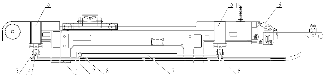
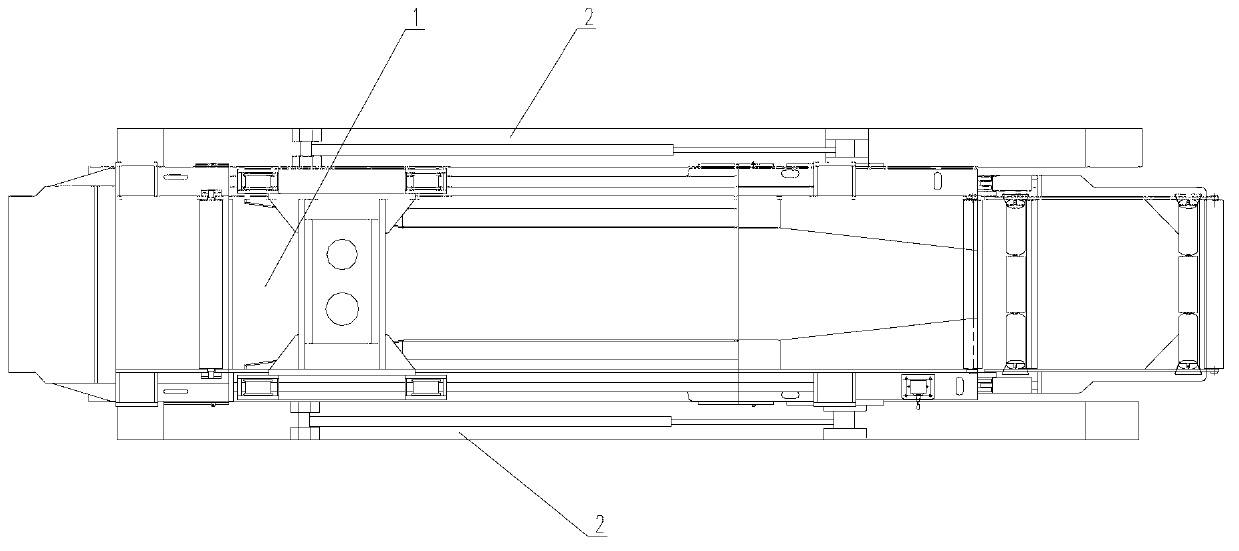
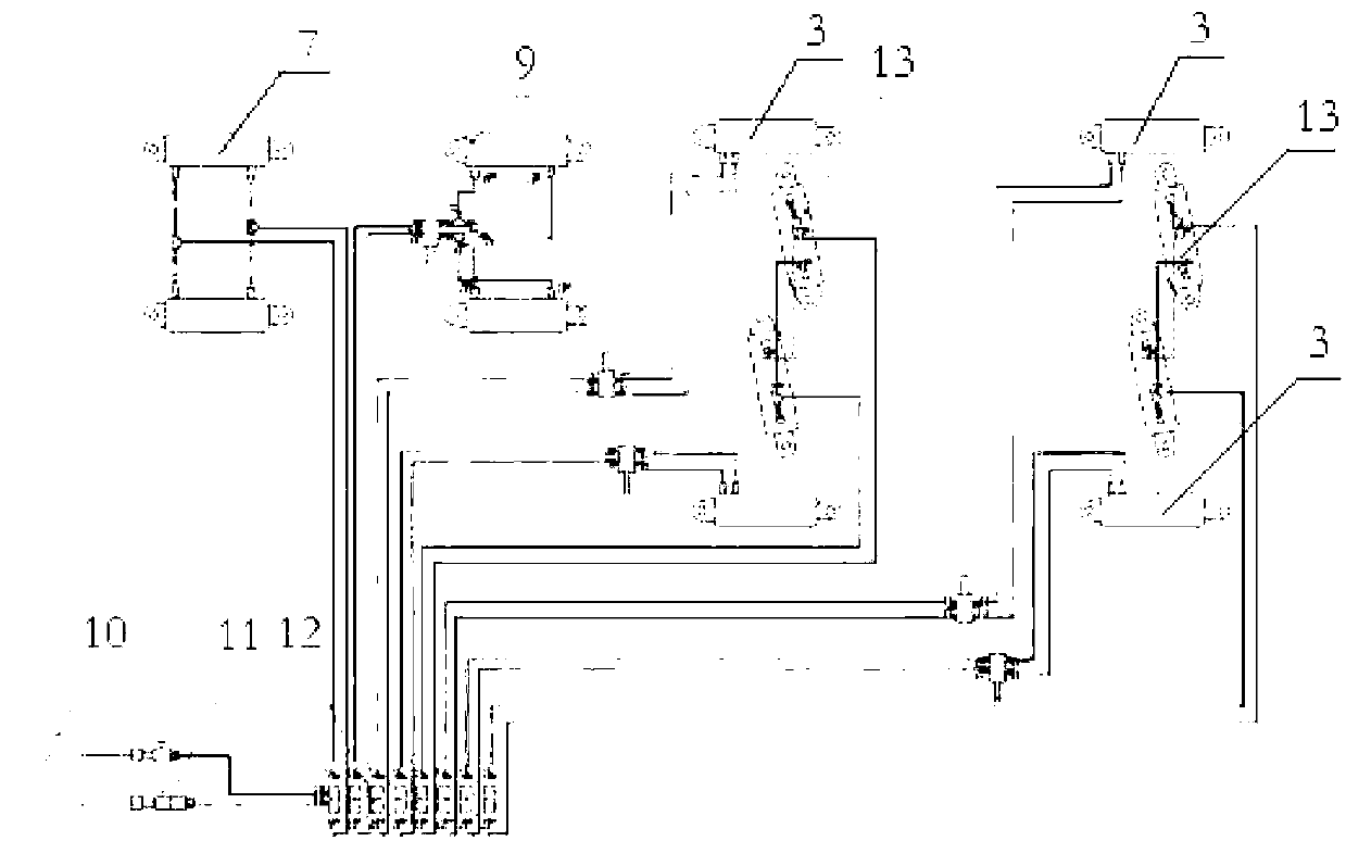
[0021] see figure 1 and figure 2 , a stepping self-moving tail device provided by the present invention is installed at the tail 1 of the belt conveyor, including guide rails 2 arranged on both sides of the tail 1 of the belt conveyor along the direction of the belt, above the guide rail 2 there is an inverted The lifting cylinder 3 on the tail 1 of the belt conveyor, the extended end of the piston rod of the lifting cylinder 3 is connected with the roller 5 that can roll along the guide rail 2 through the roller shaft 4, and the roller 5 is connected and installed with the guide rail 2 There is an anti-climbing hook 6; the top of the guide rail 2 is also horizontally provided with a push cylinder 7, the piston rod end of the push cylinder 7 is connected to the roller shaft 4 on one side, and the other end is connected to the push cylinder fixed on the guide rail 2 On the support 8; the lifting cylinder 3 and the pushing cylinder 7 are both connected with the hydraulic contr...

Embodiment 2

[0023] Present embodiment is the operating process of the present invention:

[0024] The first step is to lift the oil cylinder 3 to work, the piston rod is stretched out to make the guide rail 2 land and further support the entire belt conveyor tail 1; the second step is to push the oil cylinder 7 to work, the belt conveyor tail 1 moves forward as a whole, and the tail passes through The rolling of the roller 5 on the guide rail 2 realizes the smooth forward movement; the third step, after reaching the preset position, lift the oil cylinder 3 to retract the piston rod, and the anti-climbing hook 6 also lifts the guide rail 2 to break away from the contact with the ground. When the tail 1 of the belt conveyor is in contact with the ground, the tail can work stably; the fourth step is to push the oil cylinder 7 to work, adjust the oil inlet direction to make the cylinder move in the forward direction, and drive the guide rail 2 to move in the forward direction, for the next Mo...

Embodiment 3

[0027] see figure 1 , the tail 1 of the belt conveyor is provided with an angle adjustment oil cylinder 9 for adjusting the angle of the idler roller.


PUM


Abstract

The invention discloses an automatic-moving-type stepping machine tail device. The automatic-moving-type stepping machine tail device is installed on the machine tail of a belt machine, and comprises guide rails arranged at two sides of the machine tail of the belt machine along the belt direction; lifting oil cylinders which are inverted on the machine tail of the belt machine are arranged above the guide rails; extending ends of piston rods of the lifting oil cylinders are connected with rolling wheels capable of rolling along the guide rails through rolling wheel shafts; climbing stop hooks are connected and installed between the rolling wheels and the guide rails; a shifting oil cylinder is also horizontally arranged above the guide rails; an end of a piston rod of the shifting oil cylinder is connected to a rolling shaft at one side, and the other end of the piston rod of the shifting oil cylinder is fixed on a shifting oil cylinder support seat on the guide rails; the lifting oil cylinders and the shifting oil cylinder are all connected with a hydraulic control system. According to the invention, the machine rail moves forward through the slide friction between the rolling wheels and the guide rails, the shifting resistance is lowered greatly, and the hardness requirement of a base plate can be lowered; meanwhile, the stress situation of the machine rail can be improved, the dimensions of components of the oil cylinders and the like can be shortened; the production cost and the energy consumption can be lowered.

Description

technical field [0001] The invention relates to a matching device for coal mine underground transportation equipment, in particular to a stepping self-moving tail device for a belt conveyor. Background technique [0002] At present, a belt conveyor connected to the loader is provided on the coal mining face of the coal mine. As the loader advances, the tail of the belt conveyor needs to move accordingly. In the existing technology, most of the movement methods adopt the sliding friction between the tail shoe and the ground, which not only has a large resistance during the self-moving process, but also is prone to the phenomenon of the bottom of the shoe, which affects the safety and security of this work. work efficiency. Contents of the invention [0003] The purpose of the present invention is to overcome the above-mentioned deficiencies in the prior art, and provide a stepping self-moving tail device that can greatly reduce the dragging resistance of the tail of the be...

Claims


Application Information

Patent Timeline
Patent Type & Authority Applications(China)
IPC IPC(8): E21F13/06
Inventor 郭永存胡坤张健宋维新王鹏彧程刚
Owner ANHUI UNIV OF SCI & TECH
Why Eureka
Try Eureka