
Ternary energy-gathering floor heating system

A floor heating and energy gathering technology, applied in the field of floor heating systems, can solve problems such as heat waste, limited working efficiency of carbon crystal heating tubes, large investment in pipelines and heat exchange equipment, etc.

Inactive Publication Date: 2013-10-09
山东法斯特建材股份有限公司
View PDF0 Cites 4 Cited by
  • Summary
  • Abstract
  • Description
  • Claims
  • Application Information

AI Technical Summary

Problems solved by technology

[0002] At present, the heating system mostly uses high-heat steam provided by the heating unit, and the high-heat steam is converted into hot water through the heat exchange station and then supplied to the user. Heat loss, and steam generation equipment, pipelines and heat exchange equipment require large investment, high cost, and high user costs. At the same time, because the current heating is continuously heated 24 hours a day, most users only use it during the day or at night. This results in a lot of wasted heat
[0003] In order to solve the above problems, a household-type small-scale floor heating system has appeared. Carbon crystal heating tubes are used to heat water. Most of the water pipes are wound on the surface of the carbon crystal heating tubes for direct heating. Because the carbon crystal heating tubes can reach a temperature of 600~700℃, and water boils and vaporizes when it reaches 100℃, so if the carbon crystal heating tube is used for direct heating, the working efficiency of the carbon crystal heating tube is greatly limited; at the same time, the water tube is directly wound on the surface of the carbon crystal heating tube for heating. Heating, there is a phenomenon that the water temperature at the water inlet end of the water pipe is low and the water temperature at the water outlet end is high, resulting in inconsistent surface temperatures at both ends of the carbon crystal heating tube, which will cause damage to the carbon crystal heating tube after long-term use

Method used


Image

  • Ternary energy-gathering floor heating system
  • Ternary energy-gathering floor heating system
  • Ternary energy-gathering floor heating system

Examples


Embodiment Construction

[0023] Below in conjunction with accompanying drawing and embodiment, further elaborate the present invention. In the following detailed description, certain exemplary embodiments of the invention are described by way of illustration only. Needless to say, those skilled in the art would realize that the described embodiments can be modified in various different ways, all without departing from the spirit and scope of the present invention. Accordingly, the drawings and description are illustrative in nature and not intended to limit the scope of the claims.

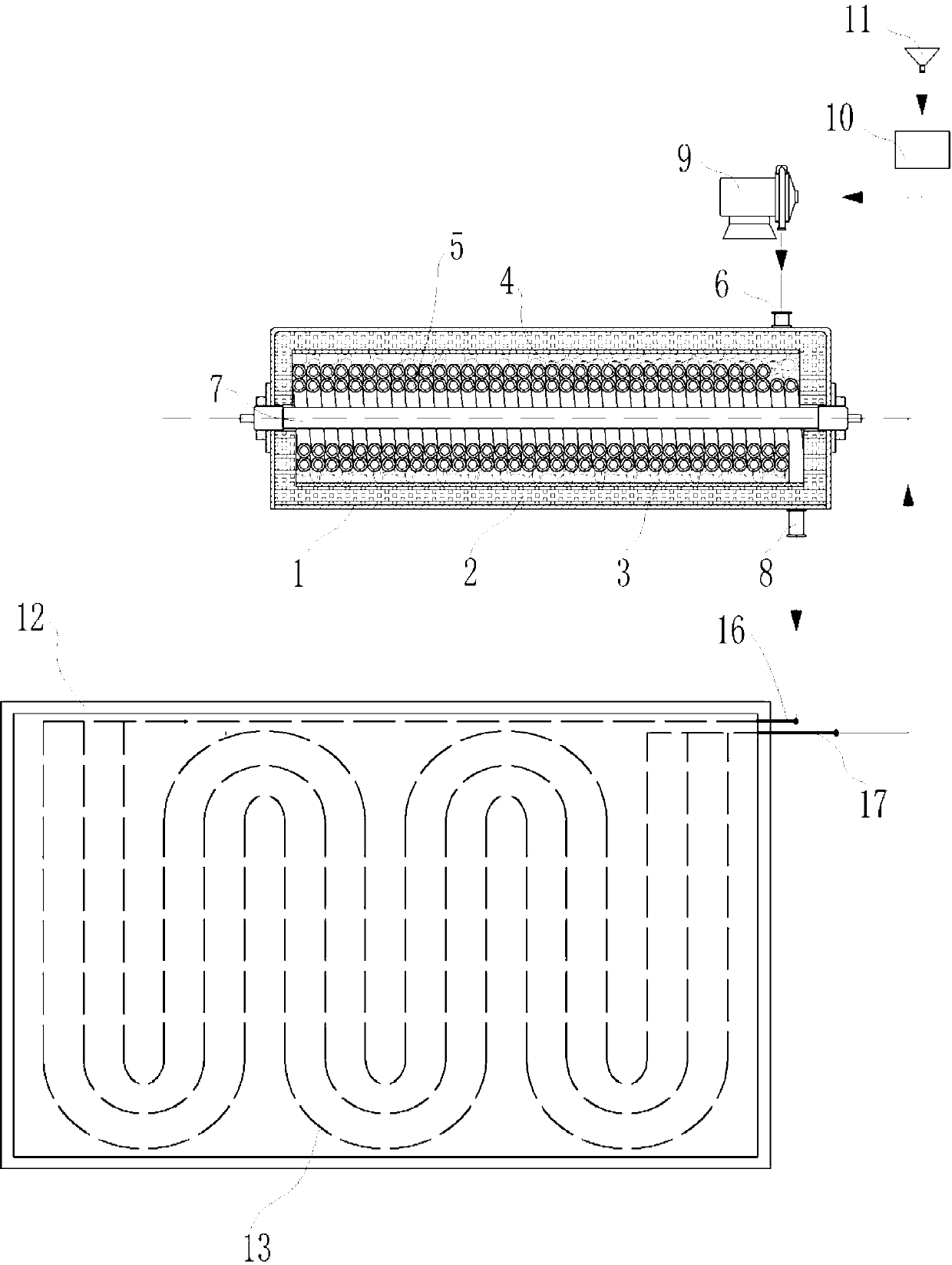
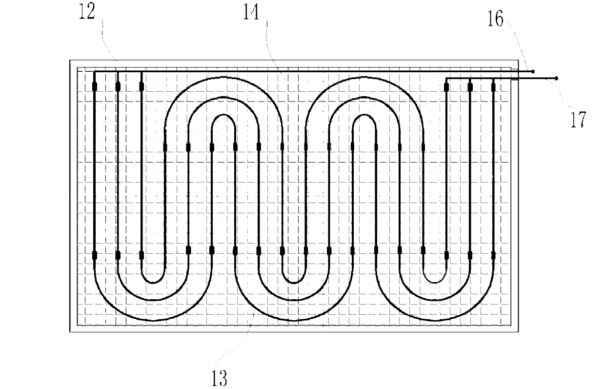
[0024] Such as figure 1 and figure 2 As shown, the three-way energy-concentrating floor heating system includes a heating shell 1, the heating shell 1 is a stainless steel shell, and a carbon crystal heating tube 7 connected to a power supply is installed in the heating shell 1, and the carbon crystal The heating tube 7 is covered with a heat exchange spiral tube 5, and the carbon crystal heating tube 7 passes throug...


PUM


Abstract

The invention discloses a ternary energy-gathering floor heating system. The ternary energy-gathering floor heating system comprises a heating shell body. A carbon crystal heating tube is installed in the heating shell body. A heat exchange spiral tube is sleeved outside the carbon crystal heating tube. Heating space is formed between the periphery side of the carbon crystal heating tube and the inner side of the heat exchange spiral tube in a partitioned mode. A heat storage buffering area, a heat reflecting layer and a heat preservation and insulation layer are sequentially arranged outside the heat exchange spiral tube. The heat exchange spiral tube is connected with a capillary network floor heating radiator. Heat radiation of the carbon crystal heating tube, heated air in the heating space and the heat storage buffering area simultaneously heat water flowing in the heat exchange spiral tube, and therefore heat of the carbon crystal heating tube is fully utilized. When operating, the carbon crystal heating tube does not make direct contact with the heat exchange spiral tube. The temperature of air in the heating space is balanced after the air in the heating space is heated. Therefore, the service life of the carbon crystal heating tube is effectively guaranteed. The ternary energy-gathering floor heating system can conveniently controls usage time, heating is convenient and flexible, and the heating cost is reduced.

Description

technical field [0001] The invention relates to a floor heating system. Background technique [0002] At present, the heating system mostly uses high-heat steam provided by the heating unit, and the high-heat steam is converted into hot water through the heat exchange station and then supplied to the user. Heat loss, and steam generation equipment, pipelines and heat exchange equipment require large investment, high cost, and high user costs. At the same time, because the current heating is continuously heated 24 hours a day, most users only use it during the day or at night. This results in a lot of wasted heat. [0003] In order to solve the above problems, a household-type small-scale floor heating system has appeared. Carbon crystal heating tubes are used to heat water. Most of the water pipes are wound on the surface of the carbon crystal heating tubes for direct heating. Because the carbon crystal heating tubes can reach a temperature of 600~700℃, and water boils and...

Claims


Application Information

Patent Timeline
IPC IPC(8): F24D12/02
CPCY02B30/00
Inventor 王勇
Owner 山东法斯特建材股份有限公司
Learn More