Novel evaluation device for performance of fiber-optic ring

A fiber optic ring, performance technology, applied in the direction of measuring device, vibration test, machine/structural component test, etc., can solve the problems of non-reciprocal phase error of fiber optic gyroscope, deterioration of thermal symmetry of fiber optic ring, increase of gyroscope temperature drift, etc. , to achieve the effect of improving quality, quick evaluation, and quick installation

Inactive Publication Date: 2013-10-09
湖南航天远望科技有限公司
View PDF7 Cites 8 Cited by
  • Summary
  • Abstract
  • Description
  • Claims
  • Application Information

AI Technical Summary

Problems solved by technology

The optical fiber ring is easily affected by environmental stress during the working process, and the refractive index change caused by the stress changes with time along the length of the optical fiber, resulting in the non-reciprocal phase error of the fiber optic gyroscope
Furthermore, in order to suppress the temperature drift of the fiber optic gyroscope, most of the fiber optic gyroscopes currently use a quadrupole symmetrical winding method to wind the fiber ring. This winding method is because the point-symmetrical parts of the fiber ring are close together, and every four layers The phase disturbances cancel each other better, and the thermal symmetry is good, which can effectively suppress the temperature drift of the fiber optic gyroscope. However, in practice, the four-pole symmetrical winding method also has non-ideal conditions such as the midpoint deviation of the fiber ring, which makes the fiber ring The thermal symmetry becomes worse, which increases the temperature drift of the gyro to a certain extent

Method used


Image

  • Novel evaluation device for performance of fiber-optic ring
  • Novel evaluation device for performance of fiber-optic ring
  • Novel evaluation device for performance of fiber-optic ring

Examples


Embodiment Construction

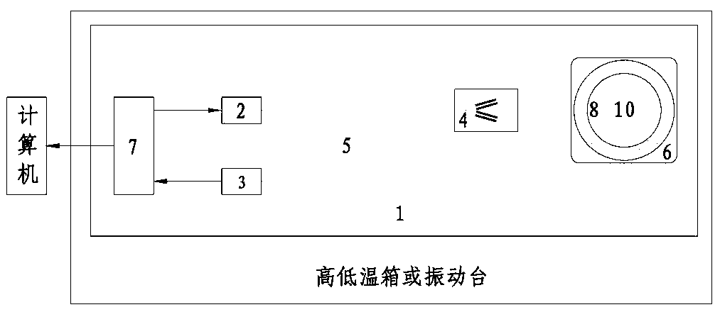
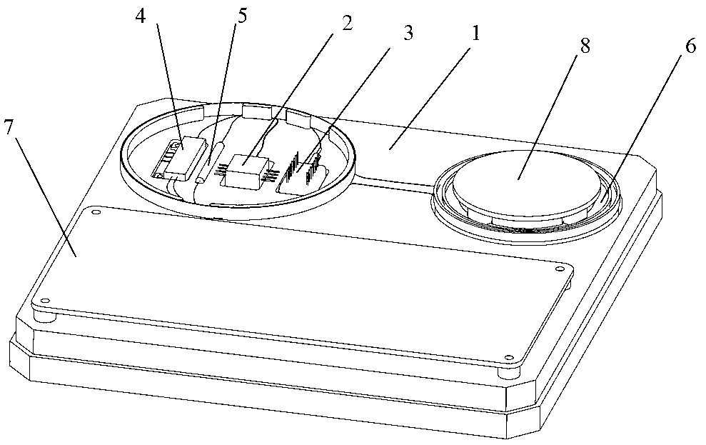
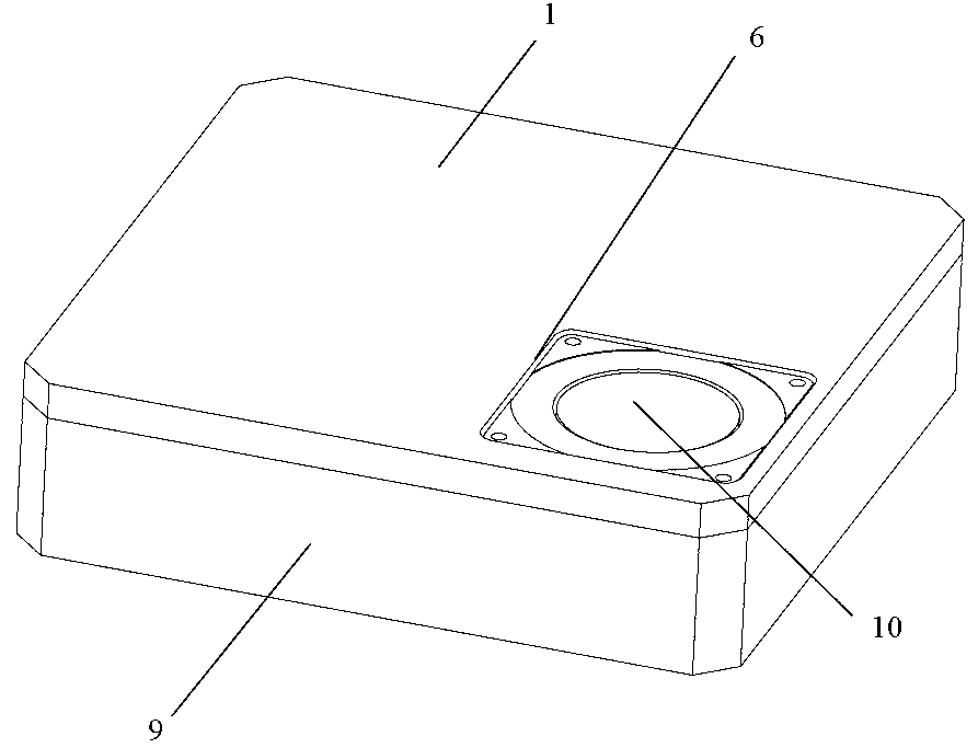
[0018] like Figure 1-5 As shown in the figure, a novel optical fiber ring performance evaluation device includes a structural body 1, an upper heating plate 8, a sealing cover (9), a lower heating plate 10, a light source 2 and a photodetector 3 fixed on the structural body 1. , Y waveguide 4, coupler 5, fiber ring component 6, drive and collection circuit board 7; the light source 2, photodetector 3, Y waveguide 4 are connected through the coupler 5, and the other end of the Y waveguide 4 is on the heating plate 8. The lower heating plate 10 is connected with the optical fiber ring member 6; the driving and collecting circuit board 7 drives the light source 2, the upper heating plate 8 and the lower heating plate 10 to work and collect the electrical signal output by the photodetector 3; The sealing cover 9 is installed on the structural body 1 ; the light source 2 is an SLD light source; the other end of the Y-waveguide 4 is welded to the optical fiber ring member 6 .

[0...


PUM


Abstract

The invention discloses a novel evaluation device for the performance of a fiber-optic ring. The novel evaluation device comprises a structure body, an upper heating piece, a sealing cover, a lower heating piece, as well as a light source, a photoelectric detector, a Y waveguide, couplers, a fiber-optic ring component, and a driving and collecting circuit board which are fixed on the structure body, wherein the light source, the photoelectric detector and the Y waveguide are connected with one another through the couplers, the other end of the Y waveguide, the upper heating piece and the lower heating piece are all connected with the fiber-optic ring component, the driving and collecting circuit board is used for driving the light source, the upper heating piece and the lower heating piece to work and collecting electrical signals output by the photoelectric detector, and the sealing cover is installed on the structure body. The novel evaluation device can be used for realizing the rapid installation and evaluation of the fiber-optic ring, greatly simplifying a detection process of the fiber-optic ring, and improving the quality of a fiber-optic gyroscope.

Description

technical field [0001] The invention relates to a novel optical fiber ring performance evaluation device, which belongs to the field of optical fiber gyro performance evaluation. Background technique [0002] The fiber optic ring is a component in the fiber optic gyroscope for the Sagnac (Sagnac) phase difference between the two counter-propagating light waves caused by the sensitive input angular velocity, so it is the main factor affecting the performance of the fiber optic gyroscope. The optical fiber ring is easily affected by environmental stress during the working process, and the refractive index change caused by the stress changes with time along the fiber length, which results in the non-reciprocal phase error of the fiber optic gyroscope. Furthermore, in order to suppress the temperature drift of the fiber optic gyroscope, most fiber optic gyroscopes currently use the quadrupole symmetrical winding method to wind the optical fiber ring. The phase disturbances canc...

Claims


Application Information

Patent Timeline
Patent Type & Authority Applications(China)
IPC IPC(8): G01C25/00G01M7/02
Inventor 岑礼君王一诚梁仁仁于中权安锋
Owner 湖南航天远望科技有限公司
Why Eureka
Try Eureka