

Optoelectronic integration block for incremental photoelectric encoder
An optoelectronic encoder and optoelectronic integration technology, applied in instruments, measuring devices, converting sensor output, etc., can solve the problems of small adaptable ambient temperature range, difficult installation and debugging, large area of photovoltaic cells, etc., to reduce uneven illumination, installation and debugging. Convenient, small photosensitive area
- Summary
- Abstract
- Description
- Claims
- Application Information
AI Technical Summary
Problems solved by technology
Method used
Image

Examples
Embodiment Construction
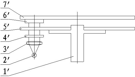
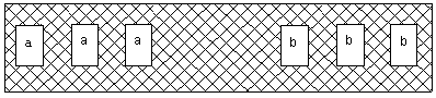
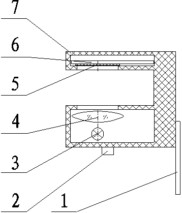
[0011] The positioning column 2 is fixedly connected to the housing 7, the lead wire 1 is fixedly connected to the housing 7, the point light source 3 and the aspheric lens 4 are respectively located inside the lower part of the housing 7, the array photocell 5 is fixedly connected to the circuit board 6, and the circuit board is located in the housing Above the inside, the structure of the photocell array is: the substrate 501 is fixedly connected to the photocell array 1 a and the photocell array 2 b with a difference of 90 degrees, the photocell array 1 a and the photocell array 2 b are arranged in a mixed manner, and the After the photovoltaic cells in each row are connected in series, each row is connected in series, and after the photovoltaic cells in each row of the photocell array 2b are connected in series, each row is connected in series.
PUM
 Abstract
Description
Claims
Application Information