Voice transmission system for wireless sensor network

A wireless sensor network and voice transmission technology, applied in voice analysis, wireless communication, advanced technology, etc., can solve the problems of complex power consumption and insufficient low power consumption, and achieve the effect of low power consumption

Inactive Publication Date: 2013-10-09
SOUTHEAST UNIV
2 Cites 2 Cited by

AI-Extracted Technical Summary

Problems solved by technology

[0007] The purpose of the present invention is to provide a voice transmission system for wireless sensor networks, which realizes low-power voice transmissio...

Abstract

Disclosed in the invention is a voice transmission system for a wireless sensor network. Voice data are converted into PCM values by a CODEC coding unit, wherein the PCM values are 24-bit data of left and right sound channels; the PCM values are transmitted to a bit conversion unit; the bit conversion unit converts the received 24-bit data of the left and right sound channels into two 14-bit left-right sound channel data; the two 14-bit left-right sound channel data are processed by a compressed encoding unit to realize lossy compression of audio data, so that the 14-bit audio data are compressed into 4-bit audio data; the 4-bit audio data are transmitted to a deserializing unit, the deserializing unit converts the 4-bit audio data outputted by the compressed encoding unit into 32-bit audio data so as to carry out bus transmission, and an enabling signal is outputted to an asynchronous FIFO, so that the asynchronous FIFO can take data; and the deserializing unit is connected with a master control unit that is in butt joint with an AHB bus, and the master control unit transmits data in the asynchronous FIFO to a designated storage zone by the AHB bus. According to the invention, a single-frequency and transient detection is removed; a voice coding requirement is ensured; low power consumption is realized; and the voice transmission system is suitable for application to a wireless sensor network to carry out voice transmission.

Application Domain

Power managementSpeech analysis +1

Technology Topic

Data conversionChannel data +15

Image

  • Voice transmission system for wireless sensor network
  • Voice transmission system for wireless sensor network
  • Voice transmission system for wireless sensor network

Examples

  • Experimental program(1)

Example Embodiment

[0030] Examples:
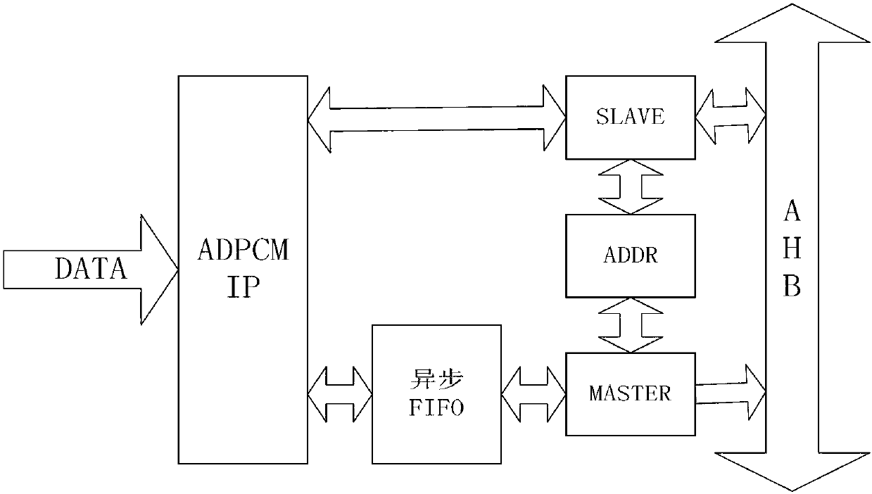
[0031] This embodiment describes a voice transmission system for a wireless sensor network. The voice data is converted into a PCM value through a CODEC encoding unit. The PCM value is 24-bit data for the left and right channels. The voice transmission system includes the number of bits. The conversion unit, compression coding unit, serial-to-parallel conversion unit and main control unit are structured as figure 1 As shown, the specific transmission process is as follows:
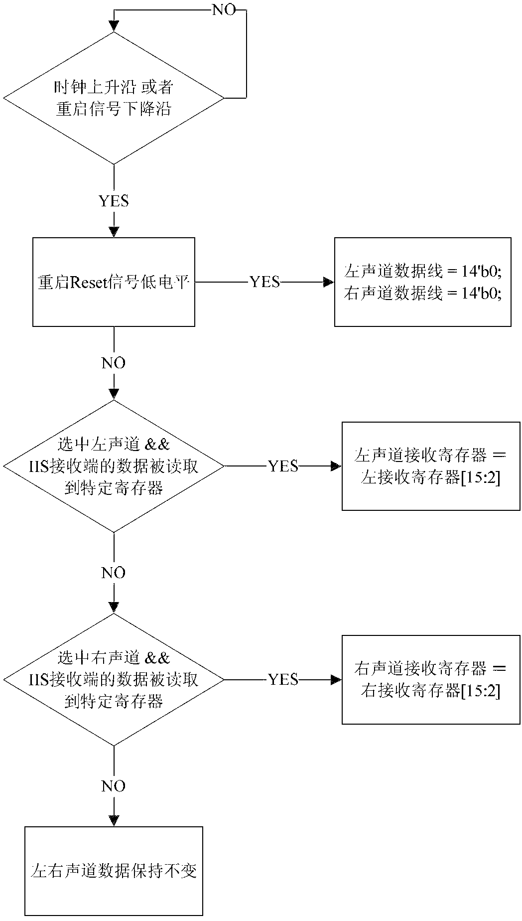
[0032] The obtained PCM value is then sent to the bit conversion unit, and the bit conversion unit converts the received 24-bit data of the left and right channels into two 14-bit left and right channel data. The workflow is as follows figure 2 Shown
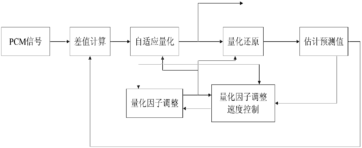
[0033] The two 14-bit left and right channel data undergo a compression encoding unit to achieve lossy compression of the audio data, and the 14-bit audio data is compressed into 4-bit audio data;
[0034] The 4-bit audio data is sent to the serial-parallel conversion unit, which converts the 4-bit audio data output by the compression encoding unit into 32-bit audio data for bus transmission, and outputs an enable signal to the asynchronous FIFO for asynchronous FIFO fetch data;
[0035] The serial-parallel conversion unit is connected with the main control unit, and the main control unit is docked with the AHB bus. The main control unit sends the data in the asynchronous FIFO to the designated storage area through the AHB bus.
[0036] As an optimization, the voice transmission system is provided with a register unit, which is configured according to the requirements of the main control unit, and the main control unit transfers data from the asynchronous FIFO to the corresponding storage area in the ESRAM.
[0037] The principle block diagram of the compression coding unit is as follows image 3 As shown, it includes a difference calculation module, an adaptive quantization module, a quantization restoration module, a predicted value estimation module, a quantization factor adjustment module, and a quantization factor adjustment speed control module. The specific encoding and compression process is as follows Figure 4 As shown, including the following steps:
[0038] The difference calculation module uses k-1 time S l And d q Call the adaptive prediction module to predict the signal estimated value S at time k e And subtract to generate a differential signal d;
[0039] Before quantization, the system calls the quantizer scaling factor and quantization factor adjustment module to calculate the quantizer scaling factor y, so that the quantizer can adapt to input signals with different statistical characteristics and different amplitudes such as voice and data;
[0040] Secondly, call the adaptive quantization module to quantize d to generate 4-bit audio data;
[0041] Then, the quantization reduction module uses the 4-bit audio data and the quantizer scale factor y to complete the inverse adaptive quantizer function, and generates the quantized differential signal d q;
[0042] Further get the reconstructed signal S r , Prepares for predicting the input signal at k+1 time and calculating Se at time k+1;
[0043] Finally, the fast and slow scale factors of the quantizer and the second and sixth-order predictor coefficients are updated at time k to complete the quantizer scale factor adaptive and adaptive speed control functions.

PUM

no PUM

Description & Claims & Application Information

We can also present the details of the Description, Claims and Application information to help users get a comprehensive understanding of the technical details of the patent, such as background art, summary of invention, brief description of drawings, description of embodiments, and other original content. On the other hand, users can also determine the specific scope of protection of the technology through the list of claims; as well as understand the changes in the life cycle of the technology with the presentation of the patent timeline. Login to view more.

Similar technology patents

Semiconductor device including capacitorless ram

ActiveUS20090310431A1reduce power consumptionretention time be lengthen
Owner:LONGITUDE LICENSING LTD

Efficient route update protocol for wireless sensor network

InactiveUS20050157698A1minimize power consumption differencereduce power consumption
Owner:SAMSUNG ELECTRONICS CO LTD +1

Lighted bollard

InactiveUS20060109667A1reduce power consumption
Owner:LEADER MFG

Classification and recommendation of technical efficacy words

  • reduce power consumption

Electrode array for use in medical stimulation and methods thereof

InactiveUS20050038489A1reduce power consumptionincrease battery life
Owner:CASE WESTERN RESERVE UNIV

Method of reselecting a cell based on priorities

ActiveUS20090181676A1ensure quality of servicereduce power consumption
Owner:LG ELECTRONICS INC

Organic light-emitting devices with mixed electron transport materials

InactiveUS20060204784A1good luminance efficiency and stabilityreduce power consumption
Owner:EASTMAN KODAK CO
Why Eureka
Try Eureka