Cross-shaped slot antenna

A cross-slot and antenna technology is applied in the field of dual-polarization high-efficiency broadband low-profile slot antennas and cross-slot antennas, which can solve the problem that the antenna is difficult to take into account dual-polarization and low profile at the same time, and achieves high aperture utilization efficiency and high profile. Low, uniform effect of aperture field distribution

Active Publication Date: 2013-10-09
BEIJING RES INST OF TELEMETRY +1
View PDF4 Cites 9 Cited by
  • Summary
  • Abstract
  • Description
  • Claims
  • Application Information

AI Technical Summary

Problems solved by technology

[0003] The purpose of the present invention is to overcome the above-mentioned deficiencies in the prior art, and provide a cross slot antenna, which solves the shortcomings ...

Method used


Image

  • Cross-shaped slot antenna
  • Cross-shaped slot antenna
  • Cross-shaped slot antenna

Examples


Embodiment Construction

[0022] Below in conjunction with accompanying drawing and specific embodiment the present invention is described in further detail:

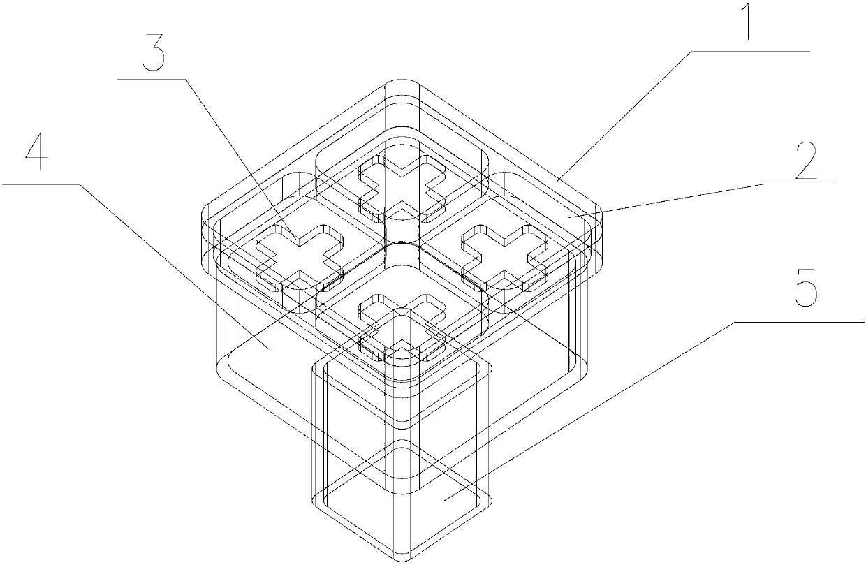
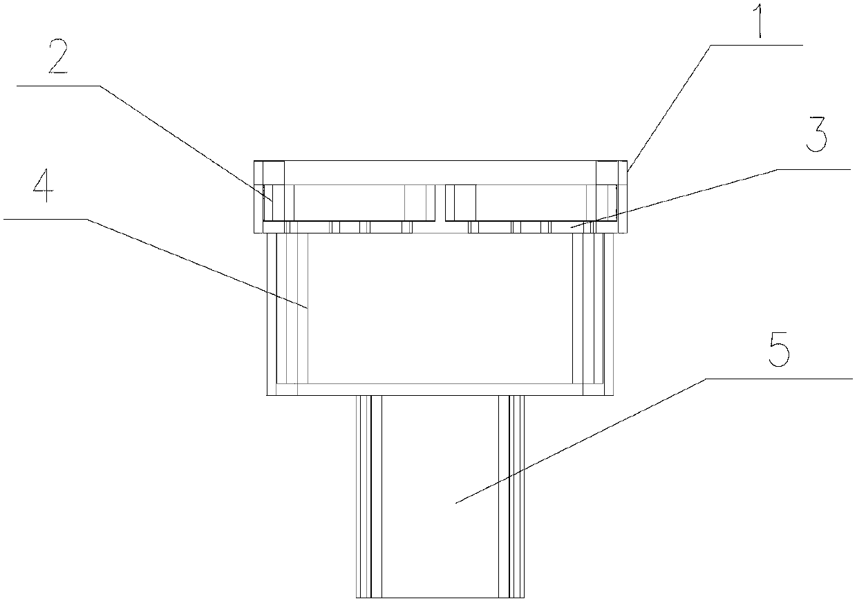
[0023] like figure 1 and figure 2 As shown, the high-efficiency cross slot antenna includes a dielectric radome 1, a radiation cavity 2, a cross slot 3, a multimode waveguide cavity 4 and a feeding square waveguide 5.

[0024] Each part is stacked sequentially from top to bottom. The uppermost layer is a dielectric radome 1; the second layer is a radiation square cavity 2; the third layer is a cross slot 3; the fourth layer is a multimode waveguide square cavity 4; the fifth layer is a feed square waveguide 5.

[0025] The dielectric radome 1 is a dielectric plate that completely covers the radiating cavity 2 and is in close contact with the radiating cavity 2 . The dielectric constant and thickness of the dielectric radome 1 are determined according to the operating frequency and bandwidth of the antenna. The dielectric radome 1 can radiat...


PUM


Abstract

The invention relates to a cross-shaped slot antenna, and belongs to the technical field of antennas. The antenna is composed of a dielectric radome, a radiating square cavity, cross-shaped slots, a multi-mode waveguide square cavity and a feed square waveguide. All the parts are arranged from top to bottom in sequence in a laminating mode. The topmost layer is a first layer which is a medium flat plate, namely, the medium dielectric radome; the second layer is formed by four metal square frames, namely, the radiating square cavity; the third layer is formed by four cross-shaped slot bodies, namely, the cross-shaped slots; the fourth layer is a metal square cavity, namely, the multi-mode waveguide square cavity; the fifth layer is a waveguide with the square cross section, namely, the feed square waveguide. The cross-shaped slot antenna is of a layered structure and can be machined in a layered mode, screws are used for connecting all the layers, and the welding technology of a traditional antenna is eliminated. The cross-shaped slot antenna is simple in structure and easier to machine.

Description

technical field [0001] The present invention relates to a cross slot antenna, in particular to a dual-polarized high-efficiency wide-band low-profile slot antenna, which can be used as the antenna unit of various dual-polarized array antennas and the feed source of dual-polarized reflector antennas. The utility model can be independently used as an antenna of various dual-polarization electronic systems, and belongs to the technical field of antennas. Background technique [0002] Antennas in high-performance electronic systems usually require dual-polarization, high efficiency, and wide-band performance at the same time. The current dual-polarized antenna generally adopts the form of a horn or a microstrip antenna. Although the horn antenna can achieve high efficiency and wide frequency band, but the antenna profile is very high, it is difficult to be used as the antenna unit of the array antenna; the microstrip antenna can also achieve wide frequency band, and the profile...

Claims


Application Information

Patent Timeline
IPC IPC(8): H01Q13/10H01Q1/42
Inventor 史永康刘昊丁晓磊
Owner BEIJING RES INST OF TELEMETRY
Why Eureka
Try Eureka