Engine automatic stop and start device, and engine automatic stop and start control method
一种自动停止起动、自动停止的技术,应用在发动机用电动机起动、发动机控制、发动机的起动等方向,能够解决无法啮合等问题,达到安静啮合的效果
- Summary
- Abstract
- Description
- Claims
- Application Information
AI Technical Summary
Problems solved by technology
Method used
Image

Examples
Embodiment approach 1
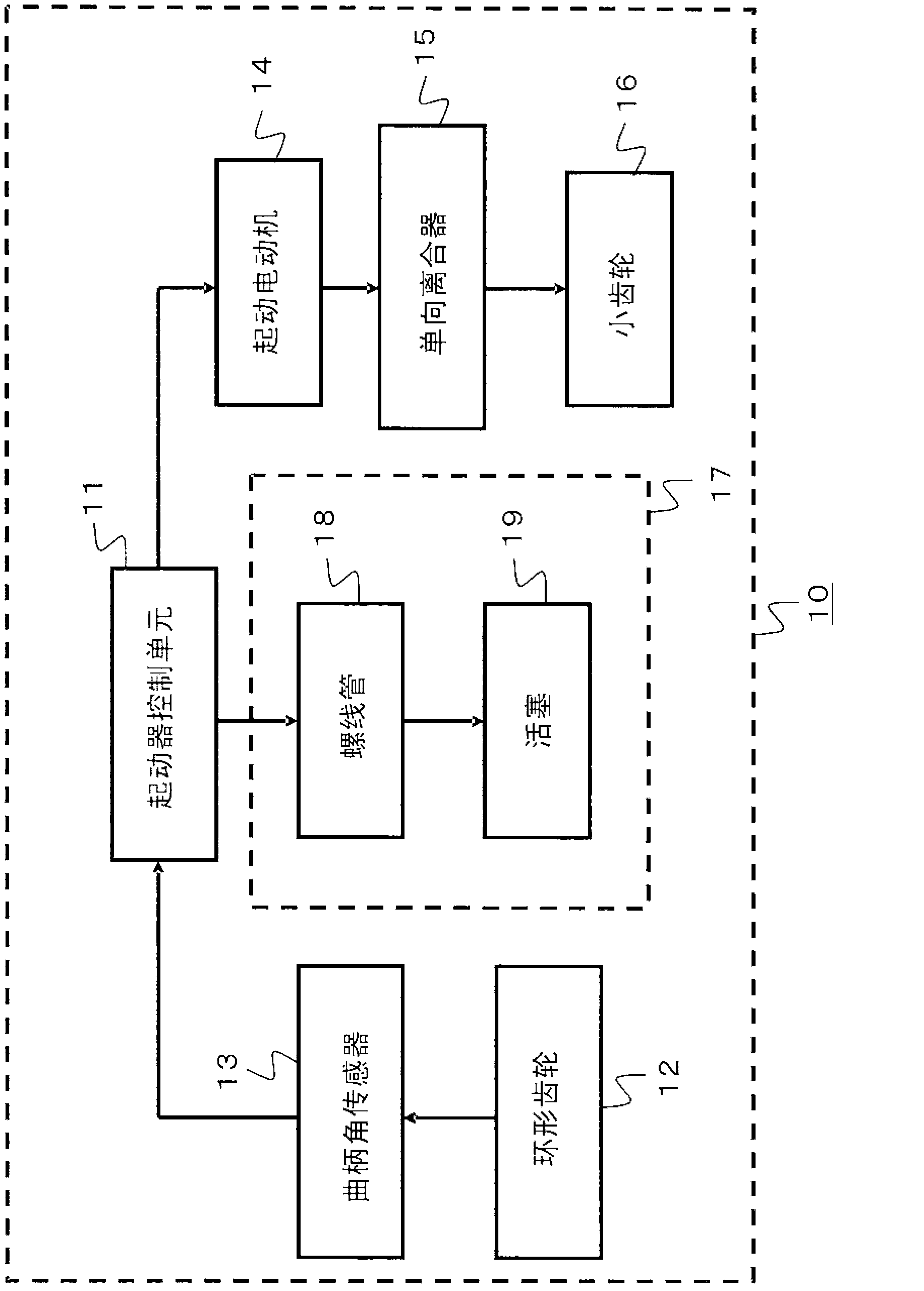
[0029] figure 1 It is a block diagram showing a schematic configuration of the engine automatic stop and start device according to Embodiment 1 of the present invention. figure 1 The engine automatic stop-start device 10 in the first embodiment shown includes a starter control unit 11 , a ring gear 12 , a crank angle sensor 13 , a starter motor 14 , a one-way clutch 15 , a pinion 16 , and a pinion moving unit 17 And constitute. In addition, the pinion moving unit 17 includes a solenoid 18 and a piston 19 .
[0030] The starter control unit 11 controls energization to the starter motor 14 and the solenoid 18 . Also, the ring gear 12 meshes with the pinion gear 16 to transmit driving force to the engine. In addition, the crank angle sensor 13 detects the crank angle of the engine. In addition, starter motor 14 rotates pinion 16 when energized.
[0031] In addition, the one-way clutch 15 is connected to the output shaft of the starter motor 14 and performs idle rotation when...
Embodiment approach 2
[0069] In the previous embodiment 1, for Figure 4 As shown, the case where energization to the starter motor 14 is temporarily stopped (corresponding to step S143 ) and energization to the solenoid 18 is started (corresponding to step S144 ) during the meshing control has been described. On the other hand, in the second embodiment, after the energization to the starter motor 14 is temporarily stopped, the energization to the solenoid 18 is started according to whether or not the solenoid energization condition (equivalent to the pinion movement condition) is satisfied. The situation will be explained.
[0070] Figure 7 It is a flowchart showing the flow of the meshing control when the engine is automatically stopped according to Embodiment 2 of the present invention. If compared with the previous embodiment 1 Figure 4 Compared with the flow chart of the present embodiment 2, the Figure 7 The difference in the flow chart of is that step S147 is newly inserted between st...
Embodiment approach 3
[0085] In Embodiment 1 and Embodiment 2 above, the case where the voltage is restored by temporarily stopping the energization to the starter motor 14 (or suppressing the current by PWM control or the like) has been described. On the other hand, in this Embodiment 3, the case where the voltage applied to the solenoid 18 is made to be more than a desired value by another method is demonstrated.
[0086] Although not shown in the figure, the engine automatic stop and start device 10 according to Embodiment 3 further includes a current suppressing circuit, a short-circuit circuit, and a switching unit. Here, the current suppression circuit corresponds to a resistor, a coil, or the like provided between the power supply and the starter motor 14 .
[0087] The short circuit corresponds to a circuit that short-circuits the current suppression circuit. Furthermore, the switching means corresponds to means for switching whether or not to short-circuit the current suppression circuit ...
PUM
 Abstract
Description
Claims
Application Information
 - R&D
- Intellectual Property
- Life Sciences
- Materials
- Tech Scout
- Unparalleled Data Quality
- Higher Quality Content
- 60% Fewer Hallucinations
Browse by: Latest US Patents, China's latest patents, Technical Efficacy Thesaurus, Application Domain, Technology Topic, Popular Technical Reports.
© 2025 PatSnap. All rights reserved.Legal|Privacy policy|Modern Slavery Act Transparency Statement|Sitemap|About US| Contact US: help@patsnap.com