Acid mist sedimentation apparatus

A settling device and acid mist technology, which is applied to the separation of dispersed particles, chemical instruments and methods, separation methods, etc., can solve problems such as environmental pollution, corrosion of surrounding equipment, hidden dangers, etc., to improve the factory and surrounding environment, reduce production costs, The effect of reducing environmental pollution

Inactive Publication Date: 2013-10-16
JIGANG GRP
6 Cites 1 Cited by

AI-Extracted Technical Summary

Problems solved by technology

The traditional exhaust gas discharge chimney originally adopts a cylindrical structure. The exhaust gas is directly discharged through the chimney, and the acid mist in the discharged exhaust gas condenses and settles around the chimney, ca...

Abstract

The invention discloses an acid mist sedimentation apparatus, which comprises a dual tapered cylindrical casing, wherein the dual tapered cylindrical casing comprises an upper tapered cylindrical casing and a lower tapered cylindrical casing, the upper end of the upper tapered cylindrical casing is provided with a gas discharge port, the lower end of the lower tapered cylindrical casing is provided with a connection port, and the connection port position is provided with a connection flange. The acid mist sedimentation apparatus is characterized in that an annular baffle is arranged inside the lower tapered cylindrical casing, the bottom of the annular baffle and the inner wall of the lower tapered cylindrical casing form a fixed connection to form an annular collection groove, the bottom of the annular collection groove is further provided with a diversion pipe, and the diversion pipe and an annular diversion groove are communicated. With the invention, the problem that peripheral equipment is corroded due to sedimentation of a large amount of acid mist in waste gas is effectively solved, important significances are provided for environmental pollution reduction and plant and surrounding environment improvement, and the collected acid liquid can be used for new acid regeneration so as to reduce a production cost and save resources.

Application Domain

Dispersed particle separation

Technology Topic

EngineeringFlange +1

Image

  • Acid mist sedimentation apparatus

Examples

  • Experimental program(1)

Example Embodiment

[0014] In order to clearly illustrate the technical characteristics of this solution, the following describes this solution through a specific implementation and in conjunction with the accompanying drawings.
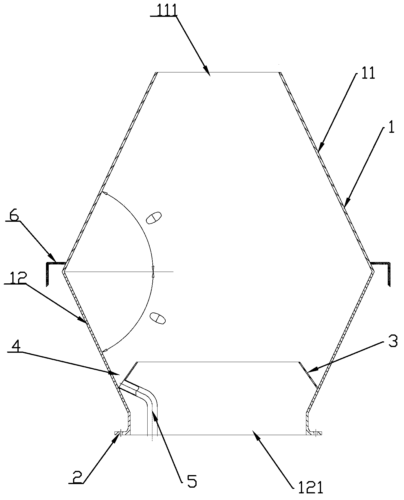
[0015] Such as figure 1 As shown, an acid mist settling device of the present invention includes a double cone-shaped cylindrical shell 1, which includes an upper cone-shaped cylindrical shell 11 and a lower cone-shaped cylindrical shell 12 The upper end of the upper conical cylindrical shell 11 is provided with an exhaust port 111, the lower end of the lower conical cylindrical shell 12 is provided with a connecting port 121, and a connecting flange 2 is provided at the connecting port 121, An annular baffle 3 is provided inside the lower conical cylindrical shell 11, and the bottom of the annular baffle 3 and the inner wall of the lower conical cylindrical shell 12 are fixedly connected to form an annular collecting groove 4, which 4 is used to collect the acid liquid formed by condensation on the inner wall of the double-cone cylindrical shell 12, the bottom of the annular collection tank 4 is also provided with a draft tube 5, the draft tube 5 and the annular guide groove 4 The acid liquid collected in the annular diversion tank 4 can flow into the waste acid collecting device for collecting acid liquid along the diversion tube 5, and the acid liquid is collected for reuse.
[0016] The outer side of the bottom of the upper conical cylindrical shell 11 is provided with an L-shaped baffle 6 along its circumferential direction. The L-shaped baffle 6 is used to divert the mist that settles outside the double-cone cylindrical shell 12 to prevent the acid from flowing along the double-conical cylindrical shell 12 to the bottom connecting flange 2 and corroding the bolts connected there.
[0017] The angles between the walls of the upper cone cylindrical shell 11 and the lower cone cylindrical shell 12 and the horizontal plane are the same. By adopting this angle design, it can be ensured that the acid liquid produced by condensation on the cylinder walls of the upper cone-shaped cylindrical shell 11 and the lower cone-shaped cylindrical shell 12 basically all fall into the annular collection tank 4.
[0018] The inner diameter of the connecting port 121 provided at the lower end of the lower cone-shaped cylindrical casing 12 is larger than the inner diameter of the exhaust port 111 provided at the upper end of the upper cone-shaped cylindrical casing 11. Such a structural design can ensure that most of the acid mist in the exhaust gas is condensed on the inner wall of the cone-shaped cylindrical shell 1 after passing through the double-conical cylindrical shell 1.
[0019] When in use, the device is connected to the top of the chimney through the connecting flange 2. The shape of the double-cone cylindrical shell 1 adopts a double-cone expansion design, and the exhaust gas enters the double-cone cylindrical shape during the discharge of the chimney. After the shell 1, because the volume suddenly increases, the airflow speed slows down, and the exhaust gas is blocked in the chimney during the rising process, the exhaust gas will condense in the double-cone cylindrical shell 1. Under the action of gravity, the droplets flow along the inner wall. The annular collection tank 4 provided in the conical cylindrical shell 1 finally flows to the waste acid collection device through the guide tube 5 connected with the annular collection tank 4 to produce acid regeneration.
[0020] Except for the technical features described in the above specification, all are the known techniques of those skilled in the art.

PUM

no PUM

Description & Claims & Application Information

We can also present the details of the Description, Claims and Application information to help users get a comprehensive understanding of the technical details of the patent, such as background art, summary of invention, brief description of drawings, description of embodiments, and other original content. On the other hand, users can also determine the specific scope of protection of the technology through the list of claims; as well as understand the changes in the life cycle of the technology with the presentation of the patent timeline. Login to view more.

Similar technology patents

Regeneration system of used clay sand

ActiveCN103521699Areduce mud contentreduce environmental pollution
Owner:QINGDAO HEDELONG MACHINERY

Method for producing biomass fuel by animal and vegetable oil leftover catalytic cracking

InactiveCN101328420Areduce environmental pollutionThe equipment is less corrosive
Owner:CHONGQING HUAZHENG ENERGY SOURCE DEV

Classification and recommendation of technical efficacy words

Why Eureka
Try Eureka