Pneumatic control assembling device of swivel joint

An assembly device and rotary joint technology, which is applied in the manufacture of tools, metal processing equipment, metal processing, etc., can solve the problems of low production efficiency, difficulty in centering, high risk factor, etc., and achieve easy operation, save manpower, and improve production efficiency. Effect

Active Publication Date: 2013-10-16
山东国能实业有限公司
View PDF8 Cites 5 Cited by
  • Summary
  • Abstract
  • Description
  • Claims
  • Application Information

AI Technical Summary

Problems solved by technology

Most of the domestic rotary joint manufacturers have original assembly methods, mainly relying on the operator to do it manually, which has problems such as low production efficiency, difficulty in centering, and high risk factor

Method used


Image

  • Pneumatic control assembling device of swivel joint
  • Pneumatic control assembling device of swivel joint

Examples


Embodiment Construction

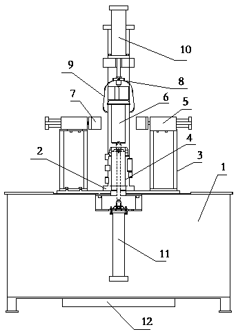
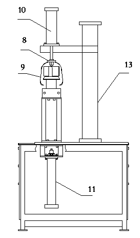
[0016] Such as figure 1 , 2 As shown, a rotary joint pneumatic control assembly device of the present invention includes a workbench 1 and a rocker arm, and an annular shell centering seat 2 is arranged on the table surface of the workbench 1 . The rotary housing 4 is placed on the housing centering seat 2, the center of the rotary housing 4 coincides with the center of the housing centering seat 2, and the rotary housing 4 is prevented from moving at the same time. The center of the centering seat 2 of the housing is provided with a central through hole passing through the table of the workbench 1. A cylinder I11 is vertically provided directly below the central through hole, and a cylinder II10 connected to the rocker arm is vertically provided directly above the central through hole. , The piston rod of cylinder I11 is opposite to the piston rod of cylinder II10. The rocker arm can move up and down, which not only saves the required space but also solves the problem that ...


PUM


Abstract

The invention discloses a pneumatic control assembling device of a swivel joint. The pneumatic control assembling device comprises a workbench and a rocker arm. The surface of the workbench is provided with an annular shell centering base, the workbench on the two sides of the shell centering base is symmetrically provided with fixing frames, and the two fixing frames are provided with opposite embracing cylinders. The ends of piston rods of the embracing cylinders are connected with V-shaped embracing blocks, and the centers of the two V-shaped embracing blocks and the center of the shell centering base are placed in the same vertical plane. The center of the shell centering base is provided with a center through hole which penetrates through the surface of the workbench. A cylinder I is vertically arranged under the center through hole, a cylinder II which is connected to the rocker arm is vertically arranged over the center through hole, and a piston rod of the cylinder I and a piston rod of the cylinder II are opposite. The pneumatic control assembling device of the swivel joint has the advantages of being simple in structure, easy to operate, saving in manpower, capable of achieving automatic centering, easier to assemble and capable of improving production efficiency.

Description

technical field [0001] The invention relates to a pneumatically controlled assembly device for a rotary joint. Background technique [0002] With the development trend of increasing production and sales of construction machinery in my country, the rotary joint as an important part of construction machinery is mainly responsible for the fixing and transportation of the entire hydraulic system pipeline, the removal of the heat transfer medium of the rotating roller, and the prevention of the hydraulic pipeline connection of the system Parts interfere during relative rotation, and their demand is increasing day by day. Most of the domestic manufacturers of rotary joints have primitive assembly methods, mainly relying on operators to do it manually, which has problems such as low production efficiency, difficulty in centering, and high risk factor. Contents of the invention [0003] In order to solve the above technical deficiencies, the present invention provides a rotary joi...

Claims


Application Information

Patent Timeline
Patent Type & Authority Applications(China)
IPC IPC(8): B23P19/00
Inventor 朱增元刘延俊赵猛李永超刘绪波何岱维
Owner 山东国能实业有限公司
Why Eureka
Try Eureka