Deformable connection structure of concrete roof and metal plate roof

A concrete and metal plate technology, applied in the direction of building components, bridge parts, bridges, etc., can solve the problems of unable to realize construction, unable to meet the gap width, unable to meet the deformation joint and other problems, and achieve the effect of simple construction and material saving.

Active Publication Date: 2013-10-16
内蒙古电力勘测设计院有限责任公司
View PDF4 Cites 1 Cited by
  • Summary
  • Abstract
  • Description
  • Claims
  • Application Information

AI Technical Summary

Problems solved by technology

The original connection structure cannot meet the treatment of deformation joints, the joint width in a large scale range, and the current requirements for building settlement, earthquake resistance and expansion.

Method used


Image

  • Deformable connection structure of concrete roof and metal plate roof

Examples


Embodiment Construction

[0016] The present invention will be further described below in conjunction with accompanying drawing.

[0017] When connecting the concrete roof and the metal plate roof, the following steps can be used.

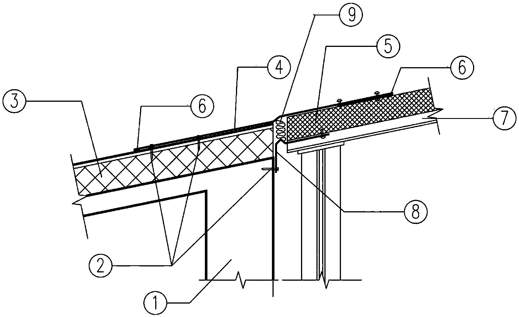
[0018] a. There is a certain gap between the concrete roof and the metal plate roof. The roof keel 7 is aligned with the beam 1 of the concrete roof. First, the iron sheet 8 is installed on the connection between the beam 1 of the concrete roof and the roof keel 7 of the metal plate roof. At the lower end, as a plug, the iron sheet is fixed on the side of the concrete beam close to the deformation joint with steel nails 2, and the iron sheet 8 is fixed on the lower end surface of the roof keel 7 of the metal plate roof with rivets, wherein the iron sheet 8 is in the deformation joint. The length is greater than the length of the deformation joint, that is, the iron sheet 8 has a certain surplus;

[0019] b. Lay the thermal insulation material 3 and the metal sandwich panel...


PUM


Abstract

The invention discloses a deformable connection structure of a concrete roof and a metal plate roof. A certain gap is reserved between the concrete roof and the metal plate roof, and an iron sheet (8) is mounted at the lower end of a connection position of a beam (1) of the concrete roof and a keel (7) of the metal plate roof; a heat insulation material (3) and a metal sandwich plate (5) are laid on a concrete plate and the roof keel (7), wherein a joint is reserved between the heat insulation material (3) and the metal sandwich plate (5) and filled with a certain filling material (9); a steel plate (4) is taken as a flashing material, stretches across the beam (1) of the concrete roof and the keel (7) of the metal plate roof, and is located above the heat insulation material (3) and the metal sandwich plate (5); and two ends of the steel plate (4) are sealed respectively with a sealing material, so that water is prevented from entering. The deformable connection structure can meet requirements for deformation joints in a large-scale project, has the functions of sedimentation, shock-proofing and expansion at the same time, and improves the drainage performance.

Description

technical field [0001] The invention relates to a wall connection structure, in particular to a deformable connection structure between a concrete roof and a metal plate roof. Background technique [0002] In the field of construction, it is often possible to encounter situations where walls need to be joined. In particular, multiple walls of different materials need to be connected to each other and meet certain requirements for strength, waterproof, and flame resistance. For example, the connection methods of doors, windows and walls mainly include steel attached frame connection, dovetail iron foot welding connection, dovetail iron foot and embedded parts connection, fixed steel sheet nailing connection, fixed steel sheet metal expansion bolt connection, etc. The connection between the doors and windows and the reinforced concrete wall can be connected by fixing steel sheets (or dovetail iron feet) with nails or metal expansion bolts. When the fixed steel sheet is used ...

Claims


Application Information

Patent Timeline
IPC IPC(8): E04B1/68E01D19/06E04F11/02
Inventor 张轩郑平吴璇
Owner 内蒙古电力勘测设计院有限责任公司
Why Eureka
Try Eureka