
Horizontally-structured framework system and construction method

A technology of horizontal structure and formwork system, which is applied in the direction of formwork/formwork/work frame, building structure, and on-site preparation of building components, which can solve the problems of low construction efficiency, high construction cost, and large labor consumption, and achieve The effect of low construction efficiency and high construction cost

Active Publication Date: 2013-10-16
SHANGHAI CONSTRUCTION GROUP +2
View PDF9 Cites 12 Cited by
  • Summary
  • Abstract
  • Description
  • Claims
  • Application Information

AI Technical Summary

Problems solved by technology

[0004] 1) High construction cost
[0005] Building a full house of scaffolding requires a lot of materials, and at the same time requires a lot of labor, and the construction cost is high;
[0006] 2) Low construction efficiency
[0007] Due to the need to set up the bent frame support and lay the bottom formwork, the workload is huge, labor-intensive and time-consuming, the construction efficiency is low, and the construction period is affected;
[0008] 3) Poor construction environment
[0014] 1) The galvanized steel plate base form is directly used in various residential and office buildings, and its cost is higher than that of pure concrete floors;
[0015] 2) It is more difficult to carry out secondary decoration on galvanized steel sheets. If the decoration of the ceiling is relatively expensive, it will take up the height space of the building;
[0016] 3) It is difficult to deal with the nodes at the junction of the truss formwork with the galvanized steel plate as the bottom formwork and the formwork of the concrete wall and concrete beam
[0017] Due to the above reasons, the self-supporting steel truss formwork is difficult to be applied in the horizontal slab structure in the pure concrete structure

Method used


Image

  • Horizontally-structured framework system and construction method
  • Horizontally-structured framework system and construction method
  • Horizontally-structured framework system and construction method

Examples


Embodiment Construction

[0045] The horizontal structure formwork system and construction method proposed by the present invention will be further described in detail below in conjunction with the accompanying drawings and specific embodiments. Advantages and features of the present invention will be apparent from the following description and claims. It should be noted that the drawings are all in a very simplified form and use imprecise ratios, which are only used to facilitate and clearly assist the purpose of illustrating the embodiments of the present invention.

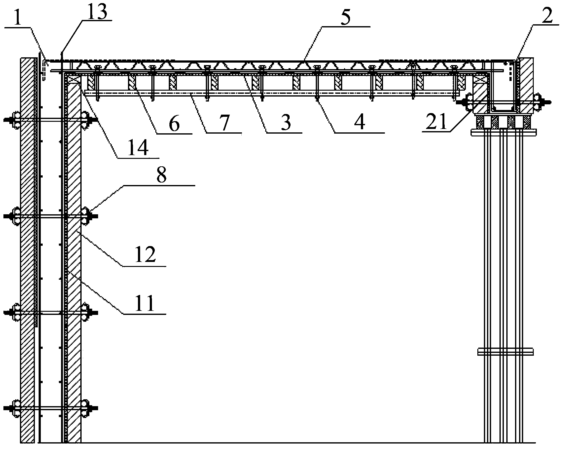
[0046]The core idea of ​​the present invention is to provide a horizontal structural formwork system and construction method, which connects the steel bar truss and the bottom formwork through connectors to form a detachable steel bar truss composite formwork, so that the system can independently bear the weight of concrete and the construction process. The additional load in the system, the force transmission route of the system is: th...


PUM


Abstract

The invention provides a horizontally-structured framework system and a construction method. A steel bar truss is connected with a soffit framework through a connecting piece to form a detachable steel bar truss composite framework, and therefore the horizontally-structured framework system can bear the self weight of concrete and additional load in the construction processes independently. The form-transmission path of the horizontally-structured framework system is that the construction load is acted on the soffit framework, is transmitted to the steel bar truss through the connecting piece, is transmitted to a vertical wood pattern or a beam framework of a side wall through the steel bar truss and is finally transmitted to a floor structure. The horizontally-structured framework system is strong in overall rigidity, the horizontally-structured framework of concrete construction is provided with no support or with few supports, backing materials and work force are saved greatly, and construction efficiency is improved at the same time.

Description

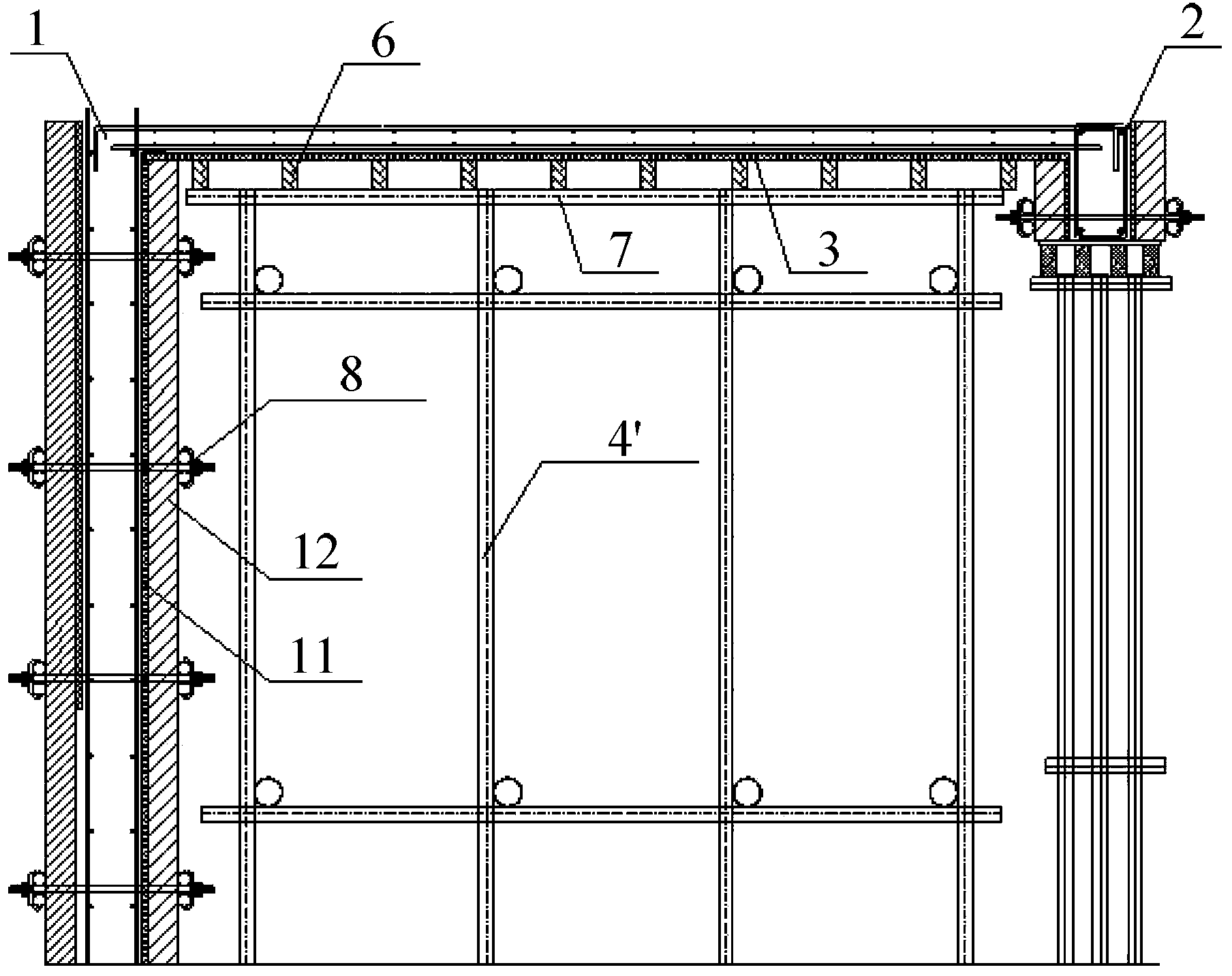
technical field [0001] The invention relates to the field of concrete structure building construction, in particular to a formwork system for a horizontal structure and a construction method. Background technique [0002] At present, horizontal structural formwork engineering in my country's construction industry generally adopts the method of erecting bent frame supports, and sequentially supporting steel pipes 7, formwork support wooden squares 6 and bottom formwork 3 for construction, such as figure 1 As shown, the process principle is to provide support for the bottom formwork 3 by setting a bent support system to meet the bearing capacity and deformation requirements during the construction stage. The bent support system is generally a full-height scaffold 4', the upper end of which is set on the steel pipe 7, The lower end rests on the concrete structure of the next floor. The bent frame support system includes: erection of Φ48×3.5 scaffolding fasteners, erection of d...

Claims


Application Information

Patent Timeline
IPC IPC(8): E04G11/36E04G11/48E04G21/00
Inventor 王美华陆云高吉龙吴杰马爱民朱敏涛
Owner SHANGHAI CONSTRUCTION GROUP
Learn More