Hydraulic cylinder provided with mechanical lock

A technology of hydraulic cylinders and cylinder barrels is applied in the field of hydraulic cylinders with mechanical locks, which can solve the damage to the hydraulic system of emergency release of external hoses, the inability of floating flanges to achieve rotational unloading, and the leakage of crude oil from external flanges. problem, to achieve the effect of good locking effect, accurate locking and opening, and long service life

Inactive Publication Date: 2013-10-16
TIANJIN HUARONG PNEUMATIC & HYDRAULIC COMPLETE SYST
View PDF0 Cites 8 Cited by
  • Summary
  • Abstract
  • Description
  • Claims
  • Application Information

AI Technical Summary

Problems solved by technology

[0002] In the prior art, the hydraulic cylinder can realize the extension and retraction actions. In applications where the hydraulic cylinder can bear high tension requirements, such as the hydraulic cylinder used for the emergency release hydraulic system of the offshore platform's external transportation hose, the positioning steel ball is generally used. To realize the locking of the hydraulic cylinder, after the above-mentioned hydraulic system has been operated for about 5-6 times, the hydraulic cylinder will not be able to lock and brake, which will lead to the leakage of crude oil exported from the floating flange during the export process. Generally, the site will use the Kalan The fixed type presses and locks the floating flange, so that the floating flange cannot realize the rotation and unloading force, so that in the event of an emergency, the emergency release hydraulic system of the external transportation hose will be damaged, posing a great potential safety hazard

Method used


Image

  • Hydraulic cylinder provided with mechanical lock
  • Hydraulic cylinder provided with mechanical lock
  • Hydraulic cylinder provided with mechanical lock

Examples


Embodiment Construction

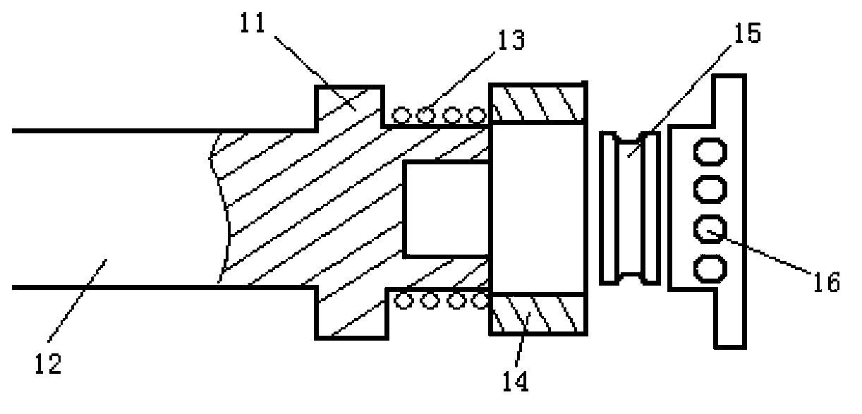
[0033] like figure 1 As shown, it is the hydraulic cylinder of the emergency release system of the external hose in the prior art. Before installation, it is subjected to a tensile test with a tensile force of 10T, and there is no abnormality. After being installed on the equipment, it repeatedly acts, causing damage to the hydraulic cylinder. The specific reasons are analyzed as follows:

[0034] When the hydraulic cylinder is retracted, oil is supplied to the front chamber of the hydraulic cylinder, the piston 11 of the hydraulic cylinder begins to retract, and the piston of the hydraulic cylinder makes the locking cylinder head contact the positioning steel ball 16 first, and the positioning steel ball is in a free state at this time. When the locking cylinder head continues to retract, The positioning steel ball 16 is pressed out by the locking column head, and the movable sleeve 14 contacts the positioning steel ball 16. Because the spring 13 behind the movable sleeve 14 ...


PUM


Abstract

The invention provides a hydraulic cylinder provided with a mechanical lock. The hydraulic cylinder comprises a cylinder barrel, a piston rod, a piston, a plunger piston, a clamping key and a clamping key seat, wherein a piston hole is formed in the piston; the plunger piston is arranged in the piston hole; a reset spring is arranged between the plunger piston and the piston; the clamping key seat is arranged at the bottom of the cylinder barrel and is a tube body with a cavity formed inside; a clamping key hole is formed in the side wall of the tube body; the clamping key comprises a circular ring and a raised key fixed on the outer spherical surface of the circular ring; the raised key is arranged in the clamping key hole; a clamp spring is arranged between the clamping key and the plunger piston; and a clamping key groove for partially accommodating the raised key is formed in the inner wall of the piston. According to the hydraulic cylinder provided with the mechanical lock, the locking effect is good, no clamping stagnation phenomenon exists in an action process, the hydraulic cylinder can be accurately locked and opened, unlocking and locking processes are guaranteed to be normal, larger tension can be borne in a locking state, and the hydraulic cylinder is not easy to damage and long in service life.

Description

technical field [0001] The invention belongs to the field of hydraulic technology, in particular to a hydraulic cylinder with a mechanical lock. Background technique [0002] In the prior art, the hydraulic cylinder can be extended and retracted. In applications where the hydraulic cylinder can withstand high tensile force, such as the hydraulic cylinder used for the emergency release of the hydraulic system for the external hose of the offshore platform, the positioning steel ball is generally used. To achieve hydraulic cylinder locking, after the above-mentioned hydraulic system is operated for about 5-6 times, the hydraulic cylinder will not be able to lock and brake, which will lead to leakage of crude oil from the floating flange during the export process. In the fixed type, the floating flange is pressed and locked, so that the floating flange cannot realize the rotational unloading force, so in the event of an emergency, the emergency release of the external hose will...

Claims


Application Information

Patent Timeline
Patent Type & Authority Applications(China)
IPC IPC(8): F15B15/26F15B15/20
Inventor 徐华生
Owner TIANJIN HUARONG PNEUMATIC & HYDRAULIC COMPLETE SYST
Why Eureka
Try Eureka