Radiator for LED lamp and method for producing radiator for LED lamp

A technology of LED lamps and production methods, applied in lighting and heating equipment, cooling/heating devices of lighting devices, lighting devices, etc., can solve problems such as difficulty in achieving automation, inability to form air convection, and unsatisfactory heat dissipation effects, etc., to achieve Eliminate welding auxiliary materials, realize continuous uninterrupted and automatic control, and quickly exchange heat with air

Inactive Publication Date: 2013-10-16
张景祥
View PDF3 Cites 0 Cited by
  • Summary
  • Abstract
  • Description
  • Claims
  • Application Information

AI Technical Summary

Problems solved by technology

[0003] At present, the bottleneck in the development of the LED lighting industry is the problem of heat dissipation. Most of the existing LED radiators on the market are extruded aluminum profiles, aluminum profiles made of sheets and fins. The production process is complicated and requires Welded one by one, or stamped through a complex process, which is inefficient and expensive
At the same time, this existing radiator structure makes its production unable to be continuous, and it is also difficult to achieve a high degree of automation
[0004] In addition, the cooling channel formed by the cooling fins of the existing radiator is blocked by itself and cannot form air convection, resulting in an unsatisfactory cooling effect

Method used


Image

  • Radiator for LED lamp and method for producing radiator for LED lamp
  • Radiator for LED lamp and method for producing radiator for LED lamp
  • Radiator for LED lamp and method for producing radiator for LED lamp

Examples


Embodiment Construction

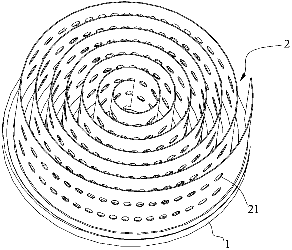
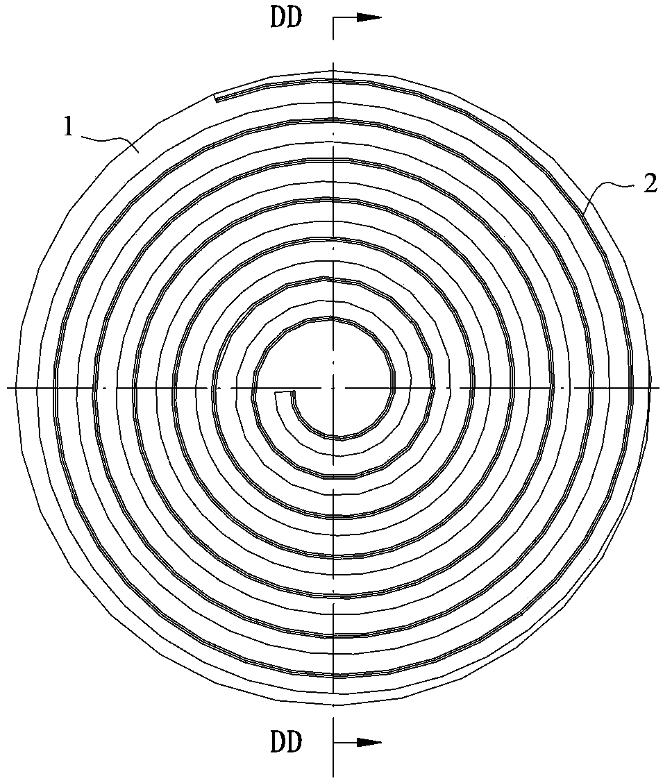
[0030] Such as Figure 1~3 The LED lamp heat sink shown includes a substrate 1 and a heat dissipation device installed on the substrate 1. The heat dissipation device is a scroll 2 formed by spiral rotation and is fixed on the surface of the substrate 1. The rotation axis of the scroll 2 is in line with the Substrate 1 intersects. Such as Figure 4 As shown, after the LED lamp 3 installed on the substrate generates heat, the heat is conducted to the scroll 2 through the substrate 1 , and the heat is dissipated through the spiral gap channel of the scroll 2 .

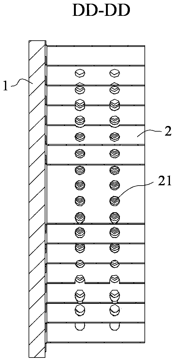
[0031] The scroll 2 of this embodiment is a strip-shaped thin plate that spirally rotates, which can be made of metal materials such as copper and aluminum, and has a plurality of through holes 21 for convection of cold and hot air on it, and the through holes 21 Arranged at equal intervals on the spiral trajectory of scroll 2. Specifically, the rotation axis of the scroll 2 is perpendicular to the base plate 1 , and ...


PUM


Abstract

The invention discloses a radiator for an LED lamp. The radiator for the LED lamp comprises a substrate and a heat dissipation device installed on the substrate. The heat dissipation device is a scroll which is formed through spiral rotation, and is fixed on the surface of the substrate, the rotation axial direction of the scroll is in intersection with the substrate, and heat dissipation is achieved through a spiral gap channel of the scroll. The invention further discloses a method for producing the radiator for the LED lamp. The method for producing the radiator for the LED lamp comprises the following steps that (S1) the substrate is fixed on a rotary shaft, wherein the substrate rotates along with the rotary shaft; (S2) a clamp is used for arranging a continuous thin plate for heat dissipation on the surface of the substrate in a spiral surrounding mode along with rotation of the substrate, and the continuous thin plate is welded on the substrate through ultrasonic bonding to form the scroll fixed on the substrate; (S3) a tool is used for cutting off the tail end of the scroll to finish production of the radiator. The radiator for the LED lamp and the method for producing the radiator for the LED lamp can achieve simple and continuous production of the radiator, reduces the size, and improves efficiency of heat dissipation.

Description

[0001] technical field [0002] The present invention relates to LED lamps, in particular to an LED lamp heat sink for LED light heat dissipation, and also relates to a production method of the above-mentioned LED light heat sink. Background technique [0003] At present, the bottleneck in the development of the LED lighting industry is the problem of heat dissipation. Most of the existing LED radiators on the market are extruded aluminum profiles, aluminum profiles made of sheets and fins. The production process is complicated and requires Welding one by one, or stamping through a complicated process, is inefficient and expensive. Simultaneously, this existing heat sink structure causes its production to be unable to be continuous, and it is also difficult to achieve a high degree of automation. [0004] In addition, the heat dissipation channel formed by the heat dissipation fins of the existing heat sink is blocked by itself and cannot form air convection, resulting in a...

Claims


Application Information

Patent Timeline
Patent Type & Authority Applications(China)
IPC IPC(8): F21V29/00F21Y101/02F21V29/83
Inventor 张景祥
Owner 张景祥
Why Eureka
Try Eureka