
Constant-current control circuit with peak current compensation and switching power supply

A constant current control circuit and peak current technology, applied in the conversion equipment with intermediate conversion to AC, conversion equipment without intermediate conversion to AC, electrical components, etc., can solve the problem of poor constant current accuracy and inaccurate peak current sampling and holding. and other problems to achieve the effect of improving consistency, improving sampling accuracy, and improving control accuracy

Active Publication Date: 2013-10-16
HANGZHOU SILAN MICROELECTRONICS
View PDF4 Cites 10 Cited by
  • Summary
  • Abstract
  • Description
  • Claims
  • Application Information

AI Technical Summary

Problems solved by technology

[0009] The technical problem to be solved by the present invention is to provide a constant current control circuit and switching power supply with peak current compensation, which can solve the problem of poor constant current accuracy caused by inaccurate peak current sampling and holding

Method used


Image

  • Constant-current control circuit with peak current compensation and switching power supply
  • Constant-current control circuit with peak current compensation and switching power supply
  • Constant-current control circuit with peak current compensation and switching power supply

Examples


Embodiment Construction

[0072] The present invention will be further described below in conjunction with specific embodiments and accompanying drawings, but the protection scope of the present invention should not be limited thereby.

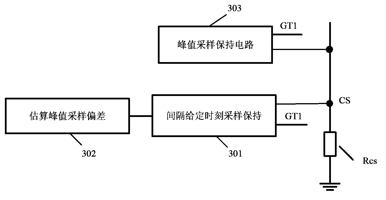
[0073] refer to image 3 , the peak current deviation generation circuit in this embodiment includes: a sample-and-hold circuit 301 at a given time interval and a peak sampling deviation estimation circuit 302 . Wherein, the sample-and-hold circuit 301 samples and holds the peak current at a given time interval according to a preset time interval, and the preset time interval is preset in proportion to the advance sampling time of the peak current by the peak sample-and-hold circuit 303, as a non-limiting example, the preset time interval is kT d , the advance sampling time of the peak sample-and-hold circuit 303 is T d , that is, the proportional coefficient between the two is k. The estimated peak sampling deviation circuit 302 calculates the preset time interval ...


PUM


Abstract

The invention provides a constant-current control circuit with peak current compensation and a switching power supply. A peak value current sampling holding circuit with compensation comprises a peak value sampling holding circuit, a peak value current deviation generation circuit, and an actual peak value calculation circuit. Specifically, the peak value current deviation generation circuit estimates a peak value current deviation of the peak value sampling holding circuit due to advanced sampling according to peak value current deviation in a preset time interval and a preset proportion; and the actual peak value calculation circuit uses the peak value current deviation obtained by the peak value current deviation generation circuit to carry out compensation on a peak value current obtained by the peak value sampling holding circuit so as to determine an actual peak value current. According to the invention, a problem of poor constant current accuracy due to inaccurate peak value current sampling holding can be solved.

Description

technical field [0001] The invention relates to switching power supply technology, in particular to a peak current deviation generating circuit, a peak current sampling and holding circuit with compensation, a constant current control circuit and a switching power supply including the peak current deviation generating circuit. Background technique [0002] refer to figure 1 , figure 1 It shows the circuit structure of applying the traditional peak sample and hold circuit to the output constant current control of the step-down structure, including the control circuit 100, the freewheeling diode D1, the power switch M1, the sampling resistor Rcs, the inductor L1 and the output capacitor C1. Wherein, the control circuit 100 includes: a peak value sampling and holding circuit 106, when the power switch M1 is turned on, sampling the sampling voltage Vcs of the peak current flowing through the power switch M1 on the sampling resistor Rcs; the output equivalent current calculation...

Claims


Application Information

Patent Timeline
IPC IPC(8): H02M1/08H02M3/10H02M3/28
Inventor 姚云龙吴建兴
Owner HANGZHOU SILAN MICROELECTRONICS
Features
  • Generate Ideas
  • Intellectual Property
  • Life Sciences
  • Materials
  • Tech Scout
  • Unparalleled Data Quality
  • Higher Quality Content
  • 60% Fewer Hallucinations
Learn More