
Visual oil-water mixing and stirring device used for laboratory

A technology of oil-water mixing and stirring devices, which is applied in the direction of mixers with rotating stirring devices, mixers, mixing methods, etc., which can solve the problems of poor repeatability, inability to see the state of the experimental medium in the kettle, and not the initial value of the experiment, etc. problem, to achieve the effect of improving experimental efficiency and accuracy, optimizing experimental design scheme, and good oil-water mixing effect

Inactive Publication Date: 2015-07-08
CHINA UNIV OF PETROLEUM (EAST CHINA)
View PDF4 Cites 0 Cited by
  • Summary
  • Abstract
  • Description
  • Claims
  • Application Information

AI Technical Summary

Problems solved by technology

[0003] Currently, research on crude oil properties for CO 2 or H 2 S corrosion effects experiments are generally carried out in high-temperature and high-pressure reactors. Due to high-temperature and high-pressure conditions, reactors are generally made of special metal materials with good airtightness. Therefore, once the experiment is started, the existence of the experimental medium in the reactor cannot be seen. , the experimental operator can only judge the oil-water mixing state in the kettle based on some experience
According to the change of water content and rotational speed (flow rate), the crude oil and water in the experimental medium may exist in a state of stratification or uneven mixing. In addition, the volume of the experimental medium added to the kettle cannot be well controlled. The volume of the input medium may be different, which may cause the sample to be completely immersed in water or crude oil. In addition, due to uneven stirring, it is possible that the water content of the crude oil where the sample is located may not be the initial value of the experiment. The above These factors may eventually lead to distortion of experimental data and poor reproducibility

Method used


Image

  • Visual oil-water mixing and stirring device used for laboratory
  • Visual oil-water mixing and stirring device used for laboratory
  • Visual oil-water mixing and stirring device used for laboratory

Examples


Embodiment Construction

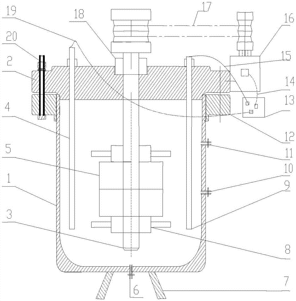
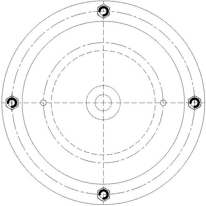
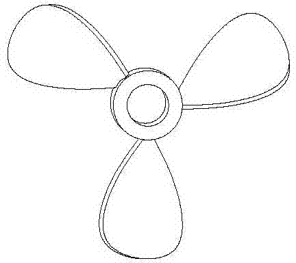
[0025] like figure 1 As shown, the visual oil-water mixing and stirring device used in the laboratory includes a kettle body 1, a kettle cover 2, a rotating shaft 3, a corrosion sample holder 5, a three-blade stirring paddle 8, a temperature and speed control box 13, and a motor 16.

[0026] The kettle body 1 is a cylindrical shell with a closed bottom and an open upper end. The kettle body 1 is equipped with crude oil and water used in the experiment. The kettle body 1 is made of transparent glass, and the mixing state of the crude oil and water in the kettle body can be directly observed; 1 is provided with an upper drain valve 11 and a middle drain valve 10, the bottom of the kettle body 1 is provided with a lower drain valve 6, and the upper drain valve 11, the middle drain valve 10 and the lower drain valve 6 are used for removing The liquid in different parts of the kettle for further determination of liquid composition. A support frame 7 is provided at the bottom of th...


PUM


Abstract

The invention relates to a visual oil-water mixing and stirring device used for a laboratory. The device comprises a kettle body, a kettle cover, a corrosion-sample clamp, three-blade stirring paddles and a temperature and rotating speed control box. A clamping sleeve is disposed outside the top of the kettle body. The kettle cover is fixed to the clamping sleeve through bolts to seal the kettle body. A vertical through hole is disposed in the center of the kettle cover. A bearing which bears a rotating shaft to rotate is fixed in the through hole. An electrical motor drives the rotating shaft to move through a conveyer belt. The lower part of the rotating shaft is provided with the corrosion-sample clamp and the two three-blade stirring paddles. The corrosion-sample clamp is sandwiched and fixed to the rotating shaft by the two three-blade stirring paddles. The three-blade stirring paddles and the corrosion-sample clamp rotate along with the rotating shaft synchronously. The kettle cover is provided with two holes. One of the two holes is provided with a heating resistance wire and the other of the two holes is provided with a thermocouple. The temperature and rotating speed control box is individually connected to the motor through a conducting wire, to the heating resistance wire through a conducting wire and to the thermocouple through a signal wire. According to the device, oil-water mixing states can be directly watched, and liquids in different parts of the kettle can be sampled for further detection.

Description

technical field [0001] The invention belongs to the field of petroleum experimental devices, and in particular relates to a visual oil-water mixing and stirring device for laboratories, which can directly view crude oil and water with a certain water content under certain rotational speed (flow rate) and certain temperature conditions. mixed state. Background technique [0002] On the properties of crude oil for CO 2 The impact of corrosion has been studied abroad in the 1990s. Most of the research results show that crude oil has obvious corrosion inhibition effect. When crude oil exists, it can greatly reduce CO 2 or H 2 Corrosion caused by S. Due to crude oil to CO 2 The complexity of corrosion effects. In the process of exploitation and gathering and transportation of many oil and gas fields, only the influence of various environmental parameters such as temperature and pressure under water phase conditions on corrosion is considered, and the influence of crude oil is...

Claims


Application Information

Patent Timeline
Patent Type & Authority Patents(China)
IPC IPC(8): B01F7/18B01F15/00B01F3/08
Inventor 孙建波孙冲张勇王勇赵卫民韩彬韩涛
Owner CHINA UNIV OF PETROLEUM (EAST CHINA)
Learn More