
Vacuum ion plating three-axis uniform speed continuous rotation coating device

A technology of vacuum ion plating and coating device, which is used in ion implantation plating, vacuum evaporation plating, sputtering plating, etc., can solve the problem that uniform rotation cannot be achieved, and the plated parts cannot be uniformly bombarded by ion beams, etc. question

Inactive Publication Date: 2015-09-09
庞厚星
View PDF4 Cites 1 Cited by
  • Summary
  • Abstract
  • Description
  • Claims
  • Application Information

AI Technical Summary

Problems solved by technology

The disadvantage of the above device is that the rhombus-shaped rotating shaft that can be installed with the plated parts does not rotate continuously but intermittently, which cannot guarantee that the plated parts can be evenly bombarded by the ion beam at any time (that is, only uniform revolution, uniform rotation, cannot achieve uniform rotation), and the third rotation axis can only be located in the same radius circle of the rotating work disk

Method used


Image

  • Vacuum ion plating three-axis uniform speed continuous rotation coating device
  • Vacuum ion plating three-axis uniform speed continuous rotation coating device
  • Vacuum ion plating three-axis uniform speed continuous rotation coating device

Examples


Embodiment Construction

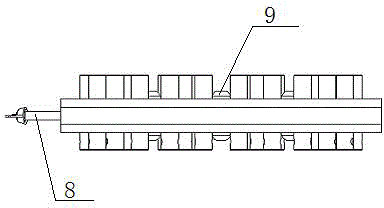
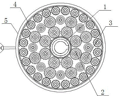
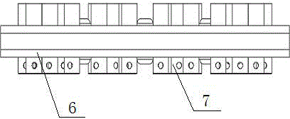
[0015] Such as figure 1 , figure 2 , image 3 and Figure 4 As shown, the vacuum ion plating three-axis uniform-speed continuous-rotation coating device is a constant-speed continuous-rotation device in which the sun gear and the ring gear jointly output the torque required for rotation and equidistantly multiplies the rotation axis, including the sun gear 1 and the inner planetary gear 2 , Transition planetary gear 3, outer planetary gear 4, ring gear 5, ring gear stop rod 8, planet carrier 6 and planet carrier fixing device 9, sun gear 1 is installed on the center position of planet carrier 6,. The inner planetary gear 2, the transitional planetary gear 3 and the outer planetary gear 4 are radially arranged between the sun gear 1 and the ring gear 5, the ring gear limit rod 8 is fixed on the ring gear 5, and the planet carrier 6 passes through the planet carrier The fixing device 9 is fixed, and the force transmission of the sun gear 1 is driven by the torque transmitted...


PUM


Abstract

The invention discloses a vacuum ion plating triaxial constant speed successive rotating coating film device. The vacuum ion plating triaxial constant speed successive rotating coating film device comprises a sun wheel, inner side planet wheels, transition planet wheels, outer side planet wheels, a gear ring, a gear ring limiting rod, a planet frame and a planet frame fixed device, wherein the sun wheel is arranged at a center position of the planet frame, the inner side planet wheels, the transition planet wheels and the outer side planet wheels are arranged between the sun wheel and the gear ring in an equal radius radioactivity manner, the gear ring limiting rod is fixed on the gear ring, and the planet frame is fixed through a planet frame fixed device. The vacuum ion plating triaxial constant speed successive rotating coating film device provided by the invention realizes the triaxial constant speed successive rotating (revolution, autoroatation and rotation) functions; the vacuum ion plating triaxial constant speed successive rotating coating film device is arranged at the axial any position of a sliding shaft at will, and the quantity is not limited; a shifting fork is canceled, the shifting fork is not needed, a rotating operation disc installing coated part can simultaneously lift or hang, the installation is simple, the lower part operation is taken, the effective space is fully utilized, and the quantity of rotating shafts is increased.

Description

technical field [0001] The invention relates to a three-axis uniform-speed continuous rotation coating device for vacuum ion plating. Background technique [0002] At present, the working turntable of the vacuum ion coating machine has three axes: the first rotating axis is the large rotating working disk axis, the second rotating axis is the movable rotating shaft, and the third rotating axis is the device axis of the plated parts of the rotating working disk. The structural principle is as follows: The deceleration motor drives the large rotating working disc shaft, and the movable rotating shaft rotates through the gear transmission. The rotating working disc is installed on the movable rotating shaft. The rotating shaft of the component undergoes angular displacement under the toggle of the fork 14 fixed on the fixed shaft (if the rotating body is hexagonal, the rotating body rotates 60 degrees every time the rotating body rotates, and if it is twelve squares, the workin...

Claims


Application Information

Patent Timeline
Patent Type & Authority Patents(China)
IPC IPC(8): C23C14/50
Inventor 庞厚星
Owner 庞厚星
Learn More