Engine starting pressure relief mechanism
A technology of engine starting and decompression mechanism, which is applied in the directions of engine starting, engine components, machines/engines, etc., can solve the problems of small effect of pulling rope pulling force, laborious starting gasoline engine, etc., and achieves easy starting, reduced gas compression ratio, Guarantee the effect of safe operation
- Summary
- Abstract
- Description
- Claims
- Application Information
AI Technical Summary
Problems solved by technology
Method used
Image
Examples
Embodiment 1
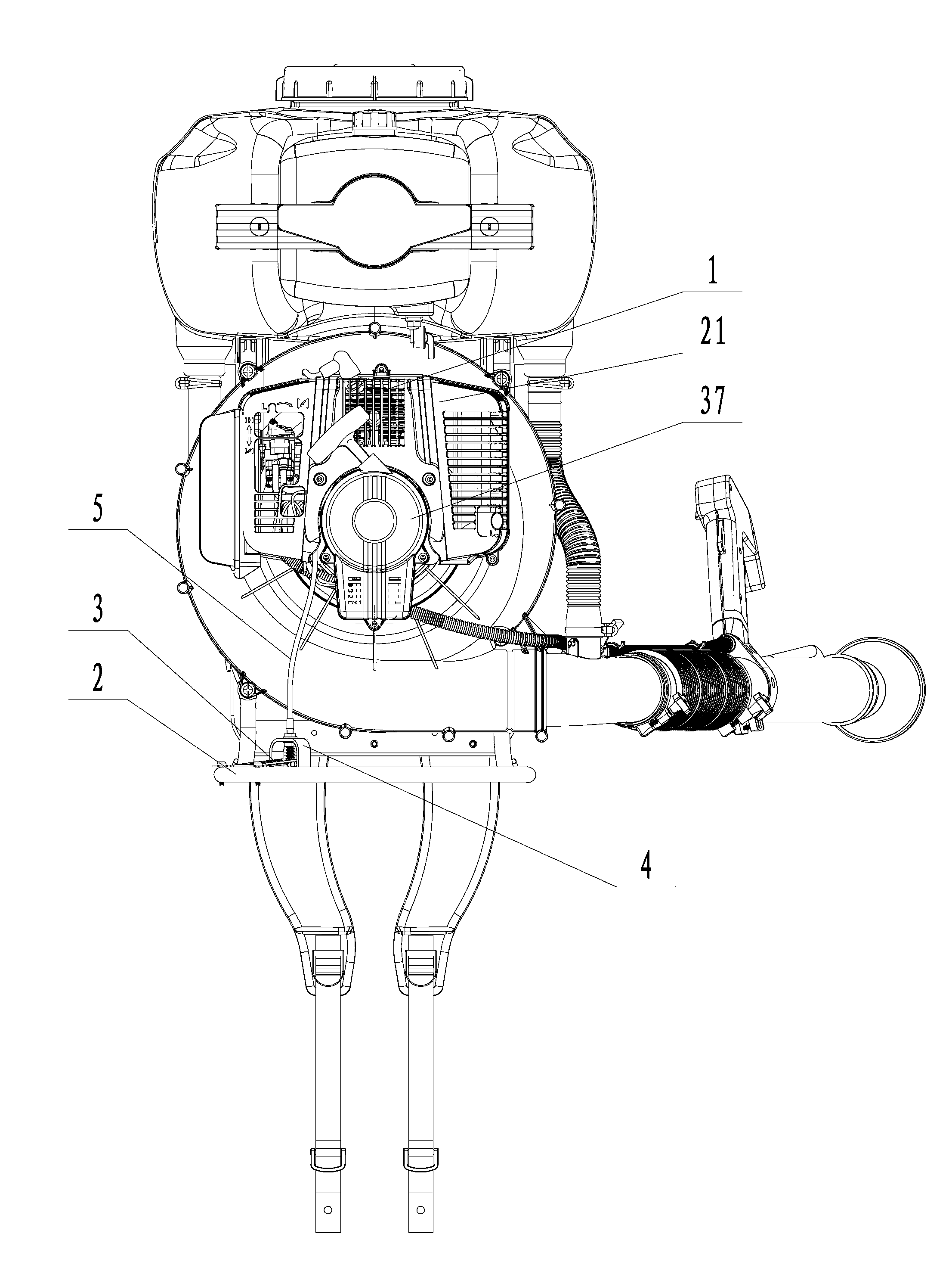
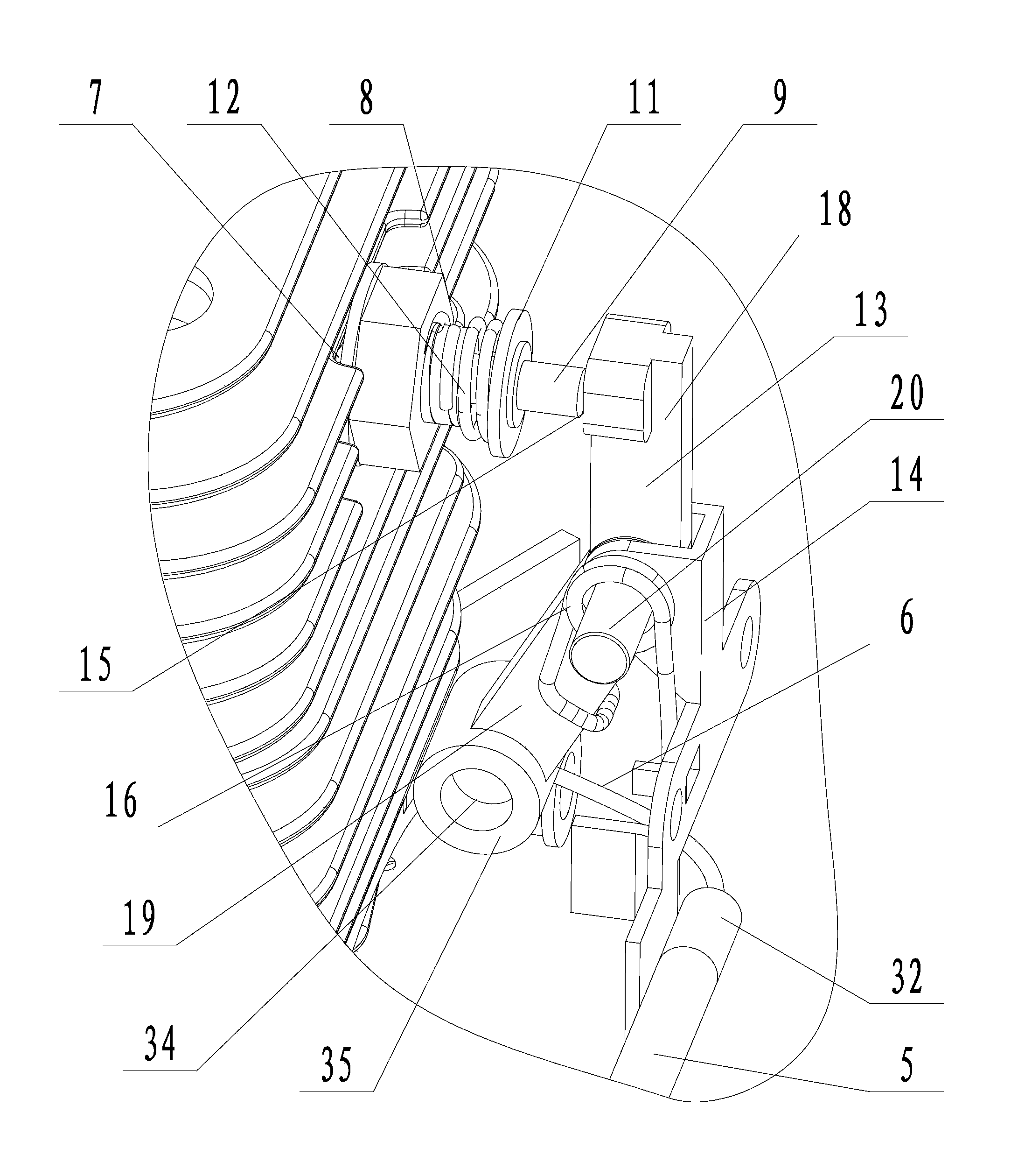
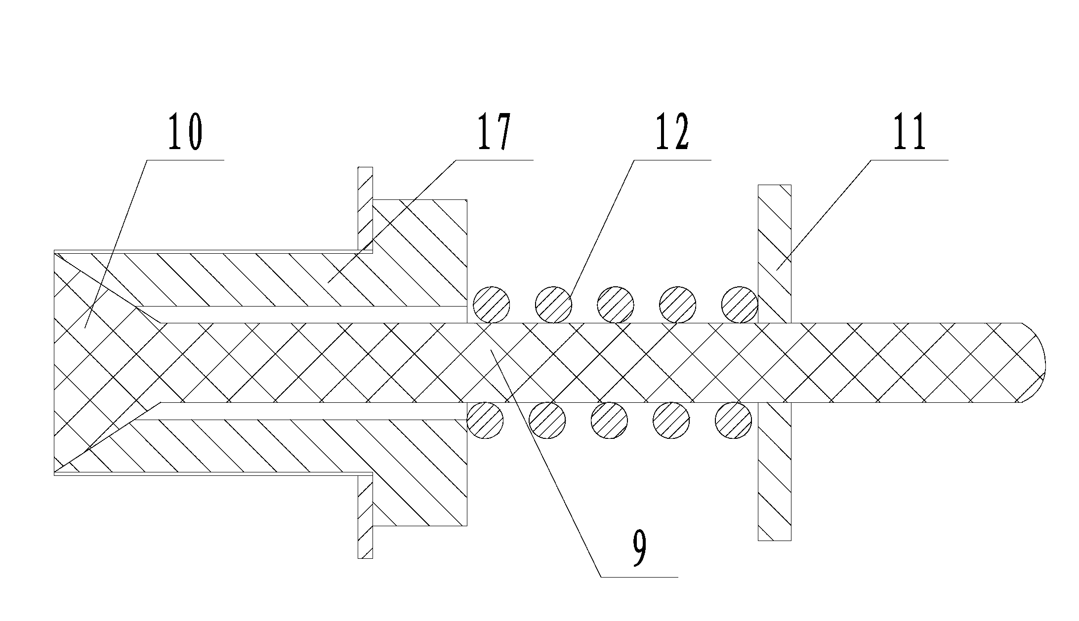
[0031] Embodiment 1: a kind of engine starts decompression mechanism, is particularly suitable for the gasoline engine on the spray duster (see attached figure 1 ), the decompression mechanism includes an engine 1, a bracket 2, a pedal 3 is hinged on the bracket, a pedal cover 4 covering the pedal is fixedly connected to the bracket, and a shaping line tube 5 is connected to the pedal cover (see attached Figure 4 ), a driving rope 6 is provided in the shaping wire tube. The driving rope is formed by twisting together several elongated steel wire ropes, and the two ends of the driving rope all extend out of the shaping wire tube and are connected with a cylindrical limiter 34 . The pedal cover has a U-shaped structure and is fixedly connected to the bracket with the opening facing down. The front end of the pedal is fixedly connected with two U-shaped connectors 37 with openings facing the rear end of the pedal. One end of the two U-shaped connectors is connected to the pedal,...
Embodiment 2
[0033] Embodiment 2: A decompression mechanism for starting an engine, its structure is similar to that of Embodiment 1, the main difference is that on the basis of the decompression mechanism of Embodiment 1, the method of operating and controlling the decompression mechanism with a rotary handle is added. In this embodiment, the spring seat is evenly distributed with two sliding holes 22 along the circumference (see the attached Figure 5 ), a U-shaped rotating frame 23 is slidably connected in the two sliding holes, and the two ends of the U-shaped rotating frame respectively pass through the two sliding holes and are respectively connected with limit nuts 24, and the bottom surface of the U-shaped rotating frame is connected with a rotating column 25 to protect The inner wall of the cover is fixedly connected with the limit column 26 near the position of the rotation column, and the rotation column is sleeved with a reset torsion spring 27, one end of the reset torsion spri...
PUM
 Abstract
Description
Claims
Application Information
 - R&D
- Intellectual Property
- Life Sciences
- Materials
- Tech Scout
- Unparalleled Data Quality
- Higher Quality Content
- 60% Fewer Hallucinations
Browse by: Latest US Patents, China's latest patents, Technical Efficacy Thesaurus, Application Domain, Technology Topic, Popular Technical Reports.
© 2025 PatSnap. All rights reserved.Legal|Privacy policy|Modern Slavery Act Transparency Statement|Sitemap|About US| Contact US: help@patsnap.com


