Engine starting pressure relief mechanism

A technology of engine starting and decompression mechanism, which is applied in the direction of engine starting, engine components, machines/engines, etc. It can solve the problems of small pulling force of the rope and laborious starting of the gasoline engine, etc., so as to achieve easy starting, lower gas compression ratio, The effect of ensuring safe operation

Active Publication Date: 2015-05-13
浙江日晟农林科技有限公司
View PDF6 Cites 0 Cited by
  • Summary
  • Abstract
  • Description
  • Claims
  • Application Information

AI Technical Summary

Problems solved by technology

Although the starting tension of the rope can be reduced by increasing the diameter of the rope pulley, it is negligible compared to the frictional resistance of the cylinder and the reaction force of the gas in the cylinder during compression, so it is very important to reduce the tension of the rope The effect is small, and it is still more laborious to start the gasoline engine

Method used


Image

  • Engine starting pressure relief mechanism
  • Engine starting pressure relief mechanism
  • Engine starting pressure relief mechanism

Examples


Embodiment 1

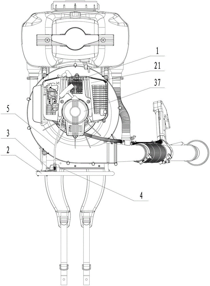
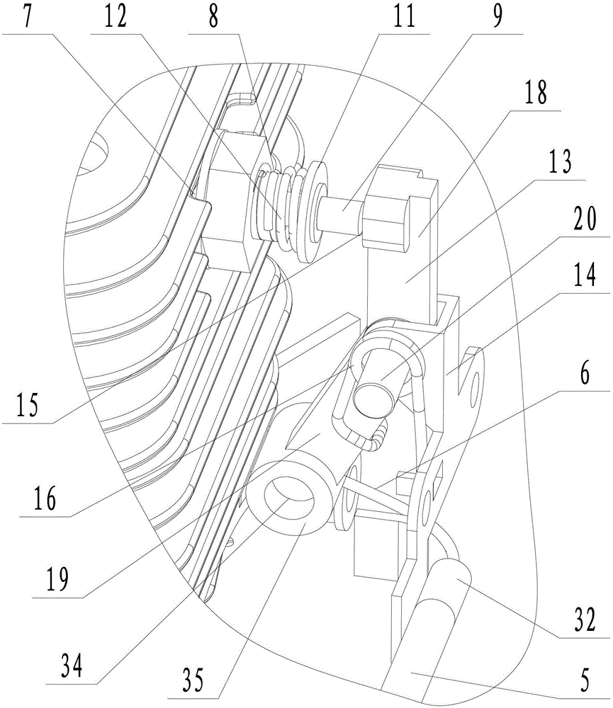
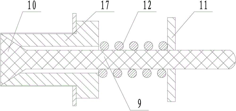
[0026] Embodiment 1: a kind of engine starts decompression mechanism, is particularly suitable for the gasoline engine on the spray duster (see attached figure 1 ), the decompression mechanism includes an engine 1, a bracket 2, a pedal 3 is hinged on the bracket, a pedal cover 4 covering the pedal is fixedly connected to the bracket, and a shaping line tube 5 is connected to the pedal cover (see attached Figure 4 ), a driving rope 6 is provided in the shaping wire tube. The driving rope is formed by twisting together several elongated steel wire ropes, and the two ends of the driving rope all extend out of the shaping wire tube and are connected with a cylindrical limiter 34 . The pedal cover has a U-shaped structure and is fixedly connected to the bracket with the opening facing down. The front end of the pedal is fixedly connected with two U-shaped connectors 37 with openings facing the rear end of the pedal. One end of the two U-shaped connectors is connected to the pedal,...

Embodiment 2

[0028] Embodiment 2: A decompression mechanism for starting an engine, its structure is similar to that of Embodiment 1, the main difference is that on the basis of the decompression mechanism of Embodiment 1, the method of operating and controlling the decompression mechanism with a rotary handle is added. In this embodiment, the spring seat is evenly distributed with two sliding holes 22 along the circumference (see the attached Figure 5 ), a U-shaped rotating frame 23 is slidably connected in the two sliding holes, and the two ends of the U-shaped rotating frame respectively pass through the two sliding holes and are respectively connected with limit nuts 24, and the bottom surface of the U-shaped rotating frame is connected with a rotating column 25 to protect The inner wall of the cover is fixedly connected with the limit column 26 near the position of the rotation column, and the rotation column is sleeved with a reset torsion spring 27, one end of the reset torsion spri...


PUM


Abstract

The invention discloses an engine starting pressure relief mechanism which aims at overcoming the defects that a recoil force of gas compression of an engine inner cavity is greater and engine starting is strenuous during the engine starting. The mechanism comprises an engine and a bracket, wherein the bracket is articulated with a pedal, and fixedly connected with a pedal cover; the pedal is covered with the pedal cover; the pedal cover is connected with a shaping line pipe; the shaping line pipe is internally provided with a driving rope; a pressure relief hole is formed in the engine, and connected with a pressure relief valve; the pressure relief valve comprises a valve rod; a valve head used for turning on and off the pressure relief valve is arranged at one end of the valve rod; the valve rod is fixedly connected with a spring seat, and is connected with a return spring in a sleeving manner; a valve rod push frame and an articulating seat are arranged in positions close to the valve rod; the valve rod push frame is articulated with the articulating seat; a push-against surface used for pushing the valve rod is arranged on the valve rod push frame; one end of the driving rope is connected with the valve rod push frame; the other end of the driving rope is connected with the pedal; and a return torsional spring is arranged between the valve rod push frame and the articulating seat.

Description

technical field [0001] The invention relates to an engine, more specifically, it relates to a start-up decompression mechanism for an engine that saves effort. Background technique [0002] Gasoline engines are widely used in various products such as water pumps, spray dusters, lawn mowers, and brush cutters. Many engines need external force to provide the starting speed required for normal engine operation during the start-up phase. This external force needs to overcome frictional resistance And the reaction force of the piston in the process of compressing the gas in the cylinder. Take the gasoline engine on the spray duster as an example. When the gasoline engine is started, the gas compression ratio in the cylinder is 6.8. When pulling the pull rope to start the gasoline engine, it is necessary to overcome the reaction force and frictional resistance during the gas compression process, so the pull rope is more laborious. If the strength is too small, the gasoline ...

Claims


Application Information

Patent Timeline
Patent Type & Authority Patents(China)
IPC IPC(8): F01L13/08F02N3/04F02N3/02
Inventor 沈焕军
Owner 浙江日晟农林科技有限公司
Why Eureka
Try Eureka