
Thermomagnetic engine and thermomagnetic engine system

An engine, thermo-magnetic technology, applied in electrical components, machines/engines, mechanical equipment, etc., can solve problems such as reducing the amount of energy conversion, ignoring kinetic energy or potential energy, etc.

Inactive Publication Date: 2013-10-23
DELTA ELECTRONICS INC
View PDF5 Cites 0 Cited by
  • Summary
  • Abstract
  • Description
  • Claims
  • Application Information

AI Technical Summary

Problems solved by technology

However, the above method only utilizes the temperature difference between the two working fluids, ignoring that the working fluid also carries a certain degree of kinetic energy or potential energy when flowing through the thermomagnetic engine, which reduces the overall energy conversion

Method used


Image

  • Thermomagnetic engine and thermomagnetic engine system
  • Thermomagnetic engine and thermomagnetic engine system
  • Thermomagnetic engine and thermomagnetic engine system

Examples


Embodiment Construction

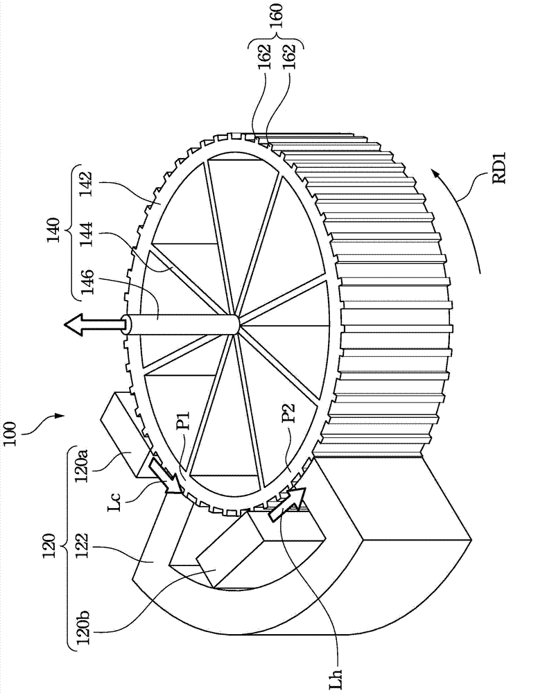
[0080] In the present invention, the rotating part of the thermomagnetic engine is provided with a fin structure. When the working fluid flows through the rotating part, the fin structure drives the rotating part to rotate in the direction of rotation based on the kinetic energy or potential energy of the working fluid flowing. In this way, the temperature difference and kinetic energy or potential energy of the working fluid can be more fully utilized to increase the overall energy conversion efficiency.

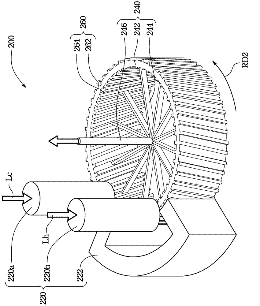
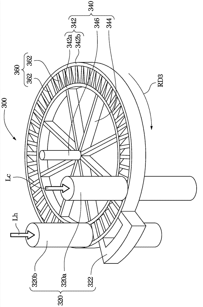
[0081] see figure 1 , figure 1 It is a schematic side view showing the internal main structure of a thermomagnetic engine 100 according to the first embodiment of the present invention. As shown in the figure, the thermomagnetic engine 100 includes a fixing member 120 (in this example, the fixing member 120 includes a low-temperature working fluid (Lc) feeding end 120a, a high-temperature working fluid (Lh) feeding end 120b, and a magnetic fixed yoke 122), Relatively rota...


PUM


Abstract

The invention discloses a thermomagnetic engine and a thermomagnetic engine system. The thermomagnetic engine comprises a fixed part, a revolving part, a working fluid and a fin structure. The revolving part comprises working materials, and the revolving part can rotate relative to the fixed part. The working fluid flows through the revolving part, enables the working materials to produce a temperature difference, and drives the revolving part to rotate in the direction of rotation. The fin structure is arranged on the revolving part, and when the working fluid flows through the revolving part, the fin structure is used for driving the revolving part to rotate in the direction of the rotation through the flowing of the working fluid.

Description

technical field [0001] The content of the present invention relates to a thermal magnetic engine and system, and in particular to a thermal magnetic engine and system with a fin structure. Background technique [0002] Since several oil crises and nuclear energy disasters, people have been actively looking for various alternative energy sources, and the main goal is to find out sustainable and low-pollution alternative energy sources. Common alternative energy sources include bioenergy (biofuel), geothermal, solar energy, wind power, tides, seawater temperature difference power generation, etc. Among them, renewable energy that can be reused is the most anticipated. [0003] Among them, the use of temperature difference (or temperature gradient) to generate or convert electrical energy or mechanical energy is one of the widely concerned renewable energy realization methods, which can use seawater temperature difference, working fluids of different temperatures or ambient te...

Claims


Application Information

Patent Timeline
IPC IPC(8): F03G7/04H02K57/00
Inventor 郭钟荣毛之成林铭赐刘玠成徐懋仁郑雅云史承彦
Owner DELTA ELECTRONICS INC
Learn More