Drive unit

A driving unit and driving gear technology, which is applied to electric vehicles, power units, motion deposition, etc., can solve the problems of the increased cost of the in-wheel motor 30 and the complex structure of the in-wheel motor 30, and achieves the realization of the number of parts and the shortening of the axial dimension. Effect

Active Publication Date: 2013-10-23
HONDA MOTOR CO LTD
View PDF7 Cites 6 Cited by
  • Summary
  • Abstract
  • Description
  • Claims
  • Application Information

AI Technical Summary

Problems solved by technology

[0007] That is, in the structure of Patent Document 1, since the motor housing 31 is filled with oil droplets, it is necessary to adopt a sealing structure, so that the structure of the hub motor 30 becomes complicated, and the cost of the hub motor 30 increases.

Method used


Image

  • Drive unit
  • Drive unit
  • Drive unit

Examples


Embodiment Construction

[0093] Hereinafter, embodiments of the present invention will be described with reference to the drawings. It should be noted that the drawings are viewed along the direction of the symbols.

[0094] 【Example】

[0095] The drive unit according to the present invention can be used as a drive source for an electric vehicle, a trolley, or an industrial machine, and its application is not particularly limited. An example of installation in an electric vehicle will be described below. Front, rear, left and right are based on the driver driving the electric vehicle.

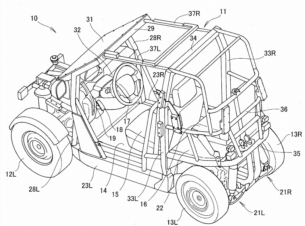
[0096] Such as figure 1 As shown, the electric vehicle 10 is a narrow vehicle, and the frame 11 is equipped with a front wheel 12L (L is a suffix indicating left. The same below) and rear wheels 13L, 13R (R is a suffix indicating right. The same below). A driver's seat 15 is provided on the floor 14, a passenger's seat 16 (Japanese: passenger's seat) is provided behind the driver's seat 15, and a steering wheel 17,...


PUM


Abstract

The present invention is concerned with a drive unit including an integrated motor and reducer, in which a sealing structure for the motor can be simplified. Oil flows through a motor-shaft oil passage (89) as shown by the arrow (3). Accordingly, the oil dose not leak into a motor case (49), so that the inside of the motor case (49) is "dry". Wires (123) extending from a stator (71) penetrate the motor case (49) and extend to the outside, but a simple seal (such as a dust seal) can be used. Thus, in the drive unit, the sealing structure for the motor can be simplified.

Description

technical field [0001] The present invention relates to a driving unit integrating an electric motor and a speed reducer. Background technique [0002] In an electric vehicle, a driving form is employed in which an output of an electric motor (hereinafter, referred to as a motor) is decelerated by a speed reducer to drive drive wheels. Both the structure in which the motor and the reducer are independently arranged and the structure in which the motor and the reducer are integrated are used in practical applications. Various structures in which the motor and the speed reducer are integrated have been proposed (for example, refer to Patent Document 1( Figure 7 )). [0003] As in Patent Document 1 Figure 7 As shown, a vehicle wheel drive device 20 (numbers in the background art indicate symbols described in Patent Document 1; the same applies hereinafter) includes an in-wheel motor 30 and a gear mechanism 50 integrated with the in-wheel motor 30 . The motor shaft 36 is rot...

Claims


Application Information

Patent Timeline
Patent Type & Authority Applications(China)
IPC IPC(8): F16H57/04F16H57/029B60K7/00
CPCB60K17/043B60K2007/0061B60G3/20F16H57/0495B60K2007/0038F16H57/043B60K7/0007B60L2220/50Y10T74/19684Y02T10/64
Inventor 小田岛贤
Owner HONDA MOTOR CO LTD
Why Eureka
Try Eureka